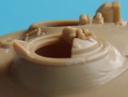
| Other changes that need to be made concerning the turret, centre around the fixtures and fittings. Firstly the commanders cupola, as can be seen in the photo below, there is some bolt detail around the rim that is missing from both the ACE and Revell kits.
Unfortunately however this detail will be difficult to replace on the Revell kit due to the Revell cupola being too shallow, the ACE kit lends itself better for the detail replacement, I also fine that the ACE cupola has better detail around the periscopes than the Revell kit.
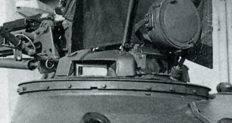
The ACE cupola has already been modified and I have made resin copies as I plan more T-72 models, the work is laborious, hence the copies. With most of the hard work to the turret now done, the electrical conduits will need to be replaced. Firstly there is the armoured conduit for the IR searchlight next to the main gun. This rises out of the turret roof just behind the RHS range finder port (as can be seen in the dimensional reference photo in part 2). Rather than following the roof contour the conduit run straight over the rangefinder port where it drops down and then follows the roof contours to the front face of the turret. The wire for the searchlight then emerges from the conduit and connects to the light itself. One note, if you are making a Czech/Polish T-72M model without the rangefinder port, this conduit also supplies the RHS smoke launchers, should they be fitted.
The LHS wiring will also need to be replaced, as noted in the comparison the wiring in the kit is simplistic at best, the wiring emerges from the turret behind the LHS rangefinder port and continues to the left into a circular junction box, from here it goes to the small searchlight mounted on a bracket next to the gunners sight, the wiring will also run to the smoke dischargers on the LHS of the turret from this point, should they be fitted.
This leaves just the wiring for the rear marker light on the turret behind the gunners hatch, here the wiring comes out of the mounting pole and into the light.
another thing to note is that the T-72 has 6 tie down loops, later models have 8. Also in the photo can be seen the gunners hatch that has been built up, both the ACE and Revell hatches are far too thin, besides the Revell hatch having no detail, as can be seen in the photo below the gunners hatch has a substantial thickness to it.
One final modification that I had to make to the turret concerns the main gun, the reshaping of the turret front now causes the kit gun not to fit properly, this can be fixed in two way. You can either blend in the existing kit piece to the turret front using putty, or you can as I did make a new canvas cover. I chose to make a new cover as beneath the canvas there is a small plate that can mostly show through, I chose to use foil and embossed the plate to the reverse side using the Part T-55 set (piece #46) with this lightly embossed onto the foil, I then cut the shape of the new canvas, I also removed the top of the moulded canvas that fit to the turret roof, the gun was then glued in place and the new canvas fitted around it and then all was blended together using putty. There is no fixed way of doing this and it is which ever method you find that suits you. After the canvas was fitted there is a small retaining wire that needs to be added to the turret roof, this runs around the top of the canvas and extends either side slightly, it is held in place by two brackets on the roof.
As can also be seen in the picture above, two hand holds need to be added, one either side, these fit low down on the turret. Also the two flat plates either side of the main gun that are present in the kit will need to be replaced as they will be lost in the reshaping. The final changes to the turret concern the rear turret bin, firstly there is a part that needs to be removed, shown by the yellow box in the picture below, this will mean that the removed wall will have to be replaced in line with the lid.
Secondly two clamps (one either side) need to be fabricated, these hold the bin in place, as the turret bin can swing upwards on the kit supplied brackets. The two clamps are placed about half way down the side of the bin and connect to the turret.
These clamps are in two parts, one half is welded to the turret and the other half to the bin, the two parts are then connected by a bolt, this is so that the turret bin can still be swung out of the way should access to the engine be required.
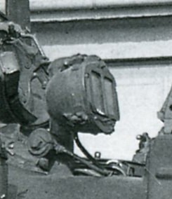
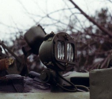
The final change that I personally made to the turret, concerns the rear facing light behind the gunners hatch, as can be seen in the pictures, the details on this light are different to all other light in the fact that the cover has 2 rectangular cut outs, normally these are coloured but have also been seen blank.
To replicate this detail, I pinched piece #26 from the Eduard T-80 PE set, this was designed to replace the fuel cell filler caps on the kit, but it has 2 rectangular cutouts and fit the light perfectly.
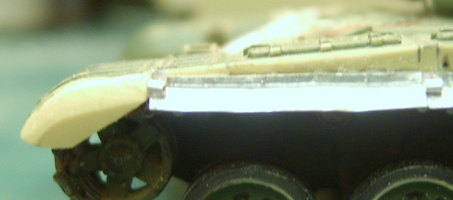
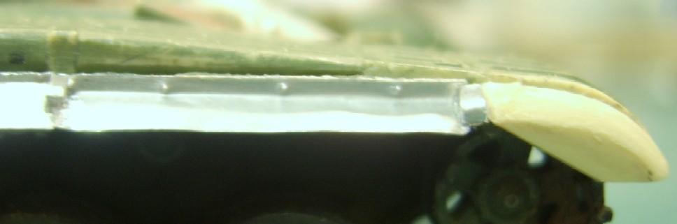
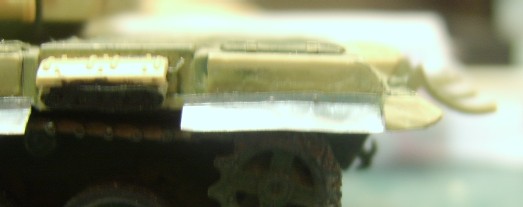
With the most of the hull and turret done, there are one or two other bits that still need to be done which are the side skirts. These can be made out of either plastic or metal foil, I preferred the foil because a, they have a nearly 90 degree bend in and with foil it is easier to show the attaching screws by simply making an indentation from the rear, not so easy are the front portion of the fenders although the kit piece can be used. I made mine out of a 4mm wide piece of foil from a metal food tray, one side is then bent up to around 60 degrees a distance of 1mm in, in the 1mm wide part the indentations are made on the reverse side.
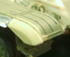
the front portion is taken from the kit side skirt, I added a 0.5mm thick piece of plasticard to the back, to make the front portion wider, this is then filed at an angle the same as the foil skirts. The other parts in the pictures are fittings for the swing out armour plates or Gill Armour as it was called.(missing from these pictures are the small square portions seen on the outside edge of the front fender)
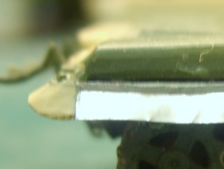
around the rear, the kit part has to be made smaller and also made to an angle, there is enough plastic to allow this.
As you can see there is a gap for the exhaust. That about completes the changes made to backdate the Revell kit. The turret changes also apply to the ACE kit, as do the hull changes, although this is more difficult due to the fact that the ACE kit has the extra armour on the glacis moulded in place, making it difficult to remove. In future articles I will be correcting the turret for the T-72M, the T-72A(T-72M1) and the T-72B, and finally I will hopefully be able to fine enough material to make the T-90 welded turret, plus all the modifications needed to make a correct T-90. A note on the fuel barrels A quick note on the Fuel barrels, the Czechs devised a system for allowing the rear fuel drums to be fed directly into the vehicle fuel system by means of hoses linking each fuel barrel to the rear right hand fuel pannier above the tracks, this system was not adopted by the Russians and so it would be wrong to model any early Russian T-72 with this system, the reason being that the Russians didn't invent it and so disregarded it. However they are now getting over the fact that it was not invented by them and have started to use the system on their own vehicles, so it is worth noting when modeling a vehicle from a specific period in time, the system has so far appeared on the T-90 and Rogatka tanks but it is also possible that it has been retro-fitted to other vehicles. |
 Revell Cupola
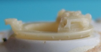 ACE Cupola
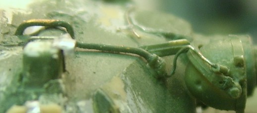 RHS wiring
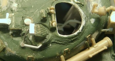 LHS wiring
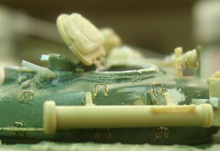 Rear marker light wiring
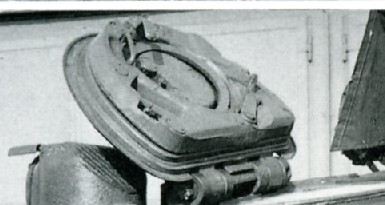 Gunners hatch.
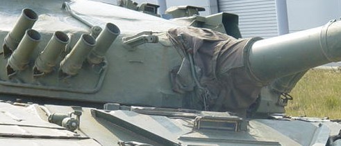 The canvas on a T-72M which has the same turret as the T-72(also
of note, is the conduit for the smoke launchers)
The canvas on a T-72M which has the same turret as the T-72(also
of note, is the conduit for the smoke launchers)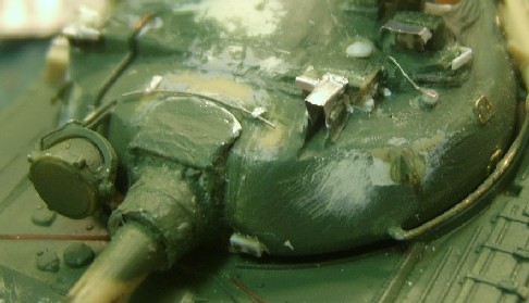 The model (one of the wire brackets has come loose in this
picture)
The model (one of the wire brackets has come loose in this
picture)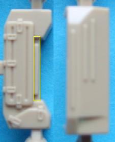 Rear bin
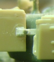 Rear bin clamps
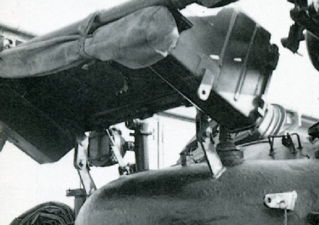 Bin hinges