www.onthewaymodels.com |
M3/M3A1 APC half-track: A comparison of the Academy, Italeri & Forces of Valour kits |
||||
| Article
by Danilo Carli
- 172normandyafv(at)gmail(dot)com Edited by Al Magnus |
|||||
www.onthewaymodels.com |
M3/M3A1 APC half-track: A comparison of the Academy, Italeri & Forces of Valour kits |
||||
| Article
by Danilo Carli
- 172normandyafv(at)gmail(dot)com Edited by Al Magnus |
|||||
|
Despite it being one of the typical Allied vehicles of the WW2, the "US half-track" was modelled for years using 1/72 inaccurate kits, until the release of the Academy M3A1 APC kit in 2004. Modellers had few choices - the inaccurate, over scale Hasegawa M3A1 APC and its M4 MMC variant, or the Airfix hybrid kit which sometimes sells as 1/72, but is actually a 1/76 kit. In 2008 Italeri released its M3 APC and M3 75 GMC kits in their "fast assembly" range. Next came the Forces of Valor M3A1 command half-track by Unimax (now by Waltersons). And lastly, PSC released its APC's M3/M3A1 and M5A1. First of all, some words about the real vehicle are needed. The M3 half-track, whose catalogue number was G102 (G147 was for the IHC M5/9/14), was produced by three companies: Autocar, Diamond T and White. Production runs went from 1941 to 1944 for a theoretical total of 12,499 M3 and 2,862 M3A1 vehicles. Anyway, when its production was discontinued, new M3A1s were made by rebuilding or upgrading other half-tracks, altering the numbers. This rebuilding practice continued after 1945 and some half-tracks were changed multiple times. For example, vehicle 4017216, which was originally an M3 75GMC, was rebuilt as an M3A1 in 1944 and then rebuilt again as an M16A1 post-WW2. Currently it is restored as an M3A1. These rebuilds make it difficult for the restoration community that often finds vehicle serial discrepancies, even between different parts on the same half-track. From a modeller's perspective, the only interesting reference is the registration number, also known as hood number, always beginning by 40 for the complete half-track production. Unfortunately, the items stored on the mudguards could hide the number, in part or completely. However, this is not a real problem. A high standardization level was required by the US Army and I didn't find any trace of differences between the builders. Various improvements were introduced during production. Visible differences were:
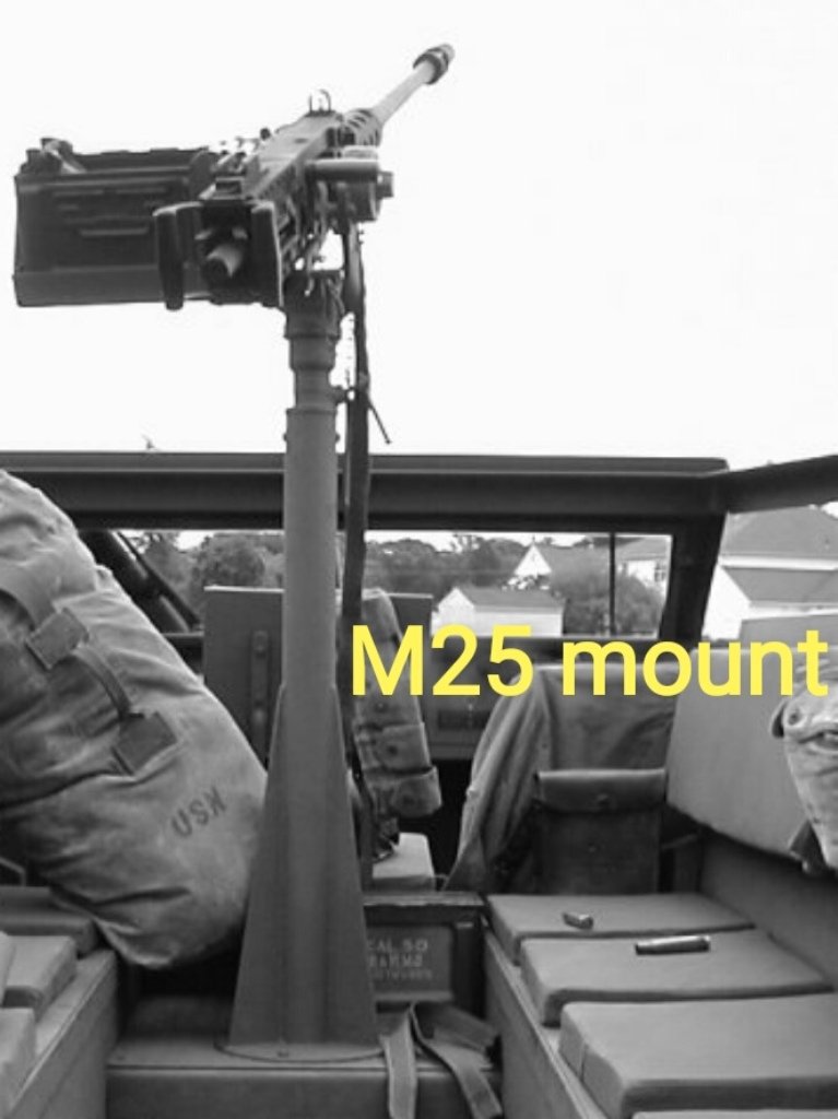
In October 1943 the M3A1 production began. It had the last M3 features and a new M49 gun mount replacing the old M25 mount. The M3A2 was to be be the next variant, but just a sole prototype was produced, and it never entered production. The most evident differentiating feature was the presence of the optional roller or winch. These were not connected to a producer or a sub variant. The winch, as well as the roller, could be a feature of a complete batch, or just a portion of it. Sub variants comprised ambulance, radio and command post types. The former is unmistakable by their huge red crosses. The latter had some radio equipment with a huge antenna base visible from outside, while its interior sported radio boxes. Externally similar to the M3 was the M21 mortar carrier. Just the 81mm mortar tip and the
M25 mount rear position reveals its identity. 110 were made by White, but I couldn't find their registration number batch (40138752, which is a very high number,
was the pilot #2).
Although I looked for a complete list I couldn't find one. Probably someone has it. I'll gladly integrate any information they can supply into the article. I used some sources to try extricating myself in the US half-track universe. I could just use the Squadron "in action" no. 34 and the Osprey "Vanguard" no. 31 and the "New Vanguard" no. 11. Data, info and details can be seen here: afvdb. I also used technical manuals TM 9-710 for the M3/M3A1, TM 9-707 for the M5-M9 variants and TM 9-224 for the M25 gun mount. Field manual FM 8-35 was used for the ambulance variant. I guess there are surely other good sources, but with a limited budget I didn't search for them. A good walkaround is here: usarmymodels.com. Now that we have looked at the variants, let's take a look at dimensions.
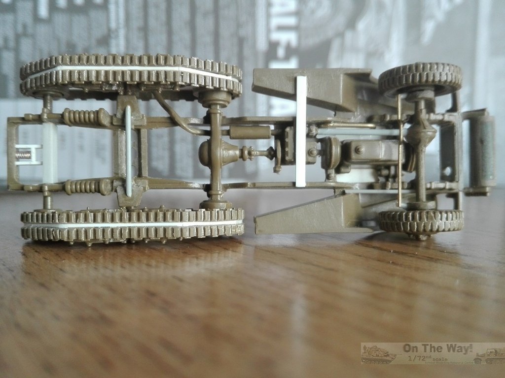
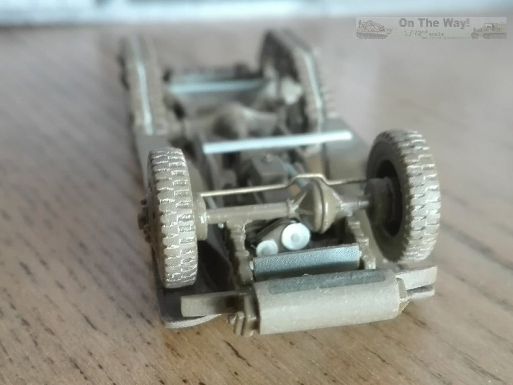
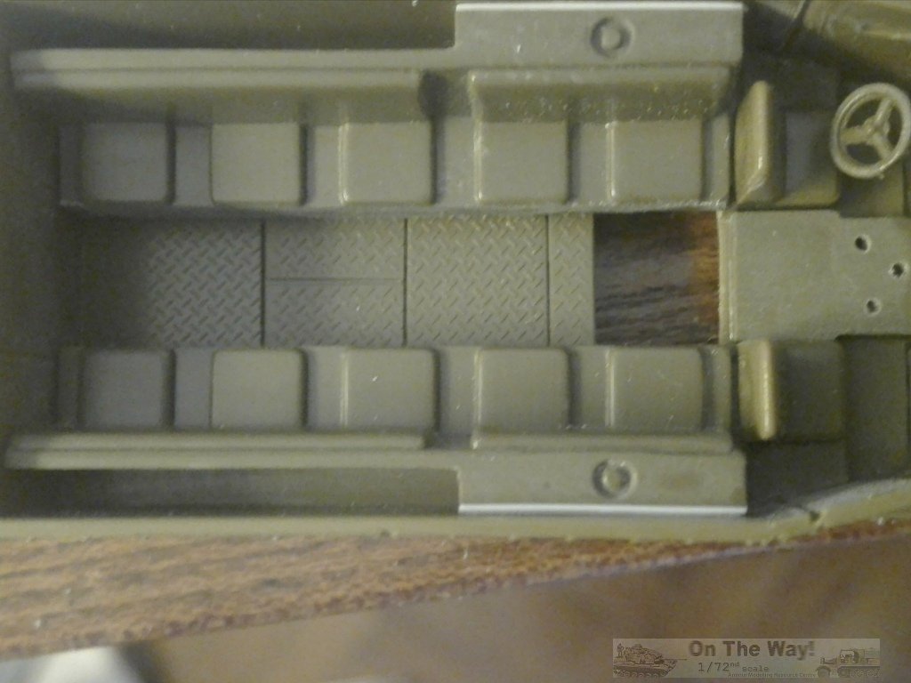
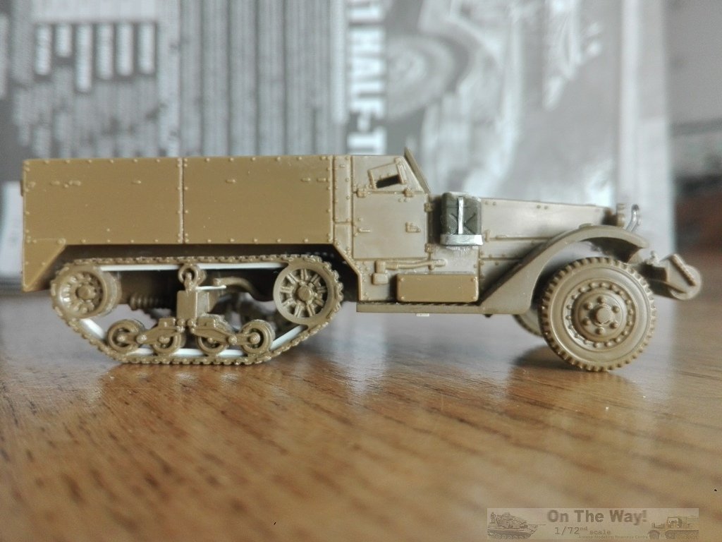
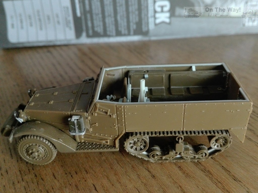
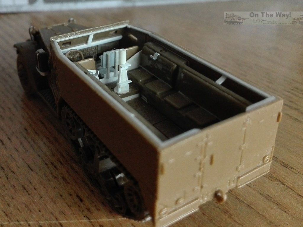
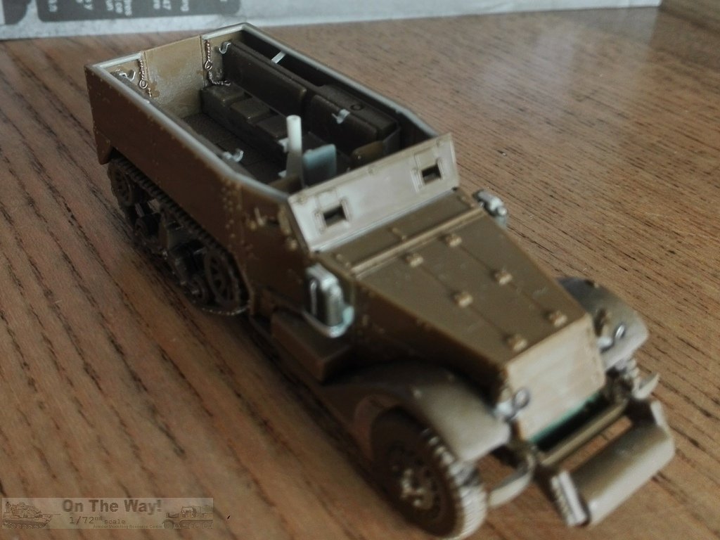
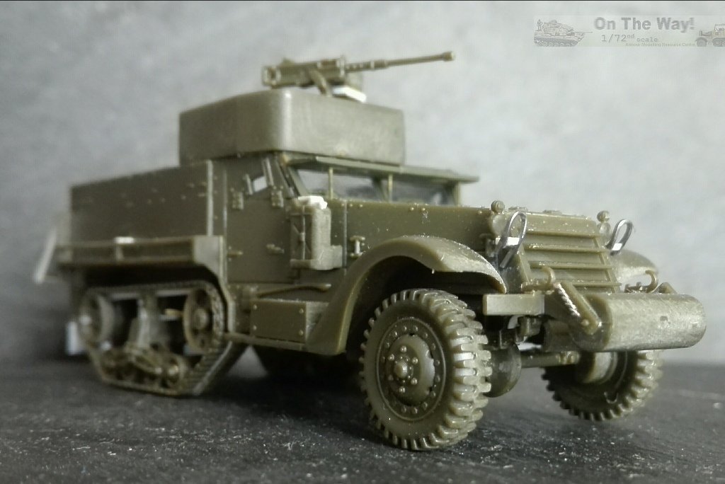
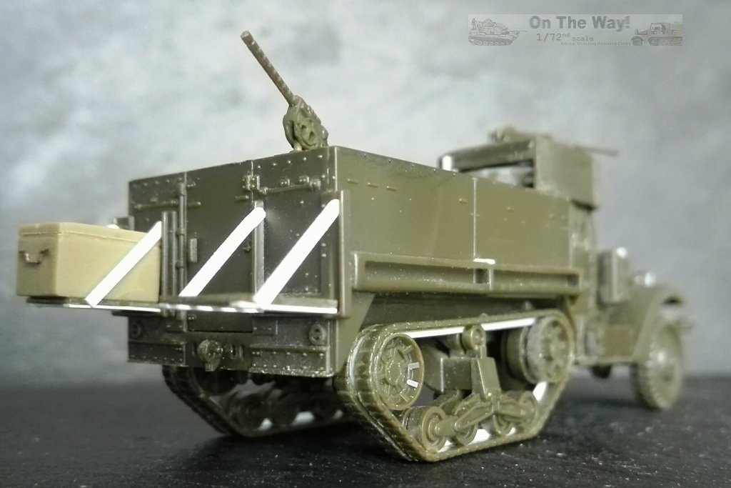
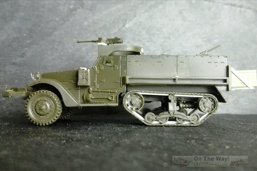
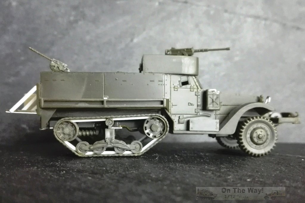
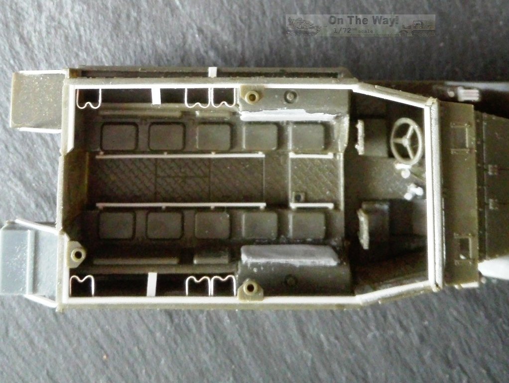
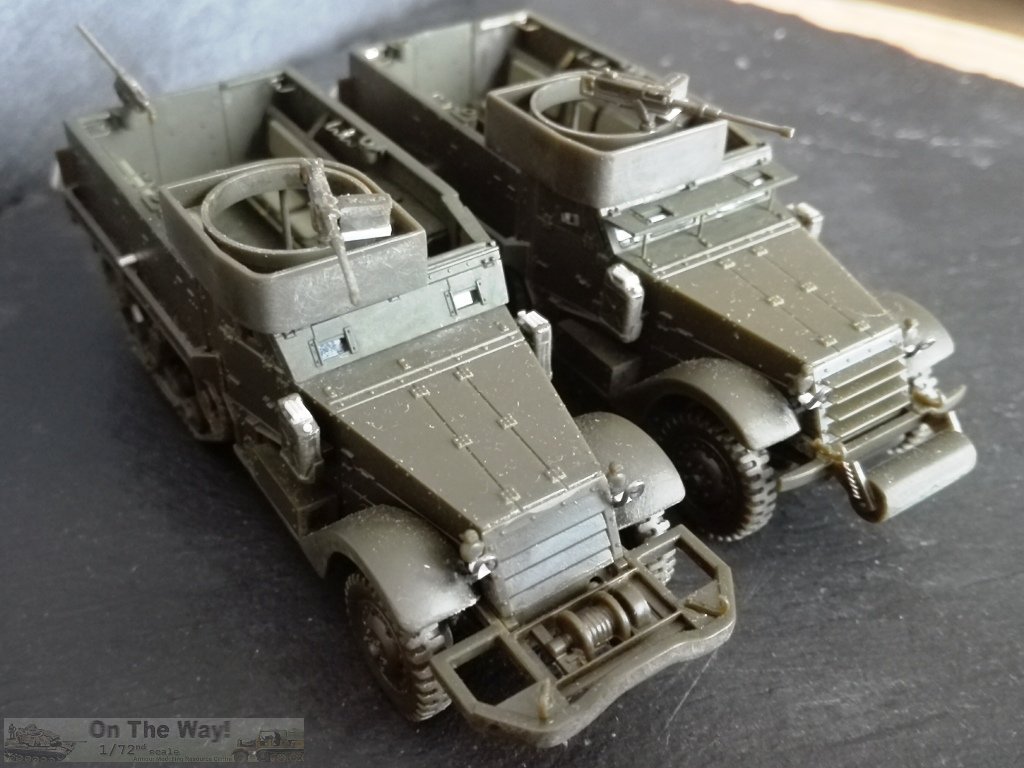
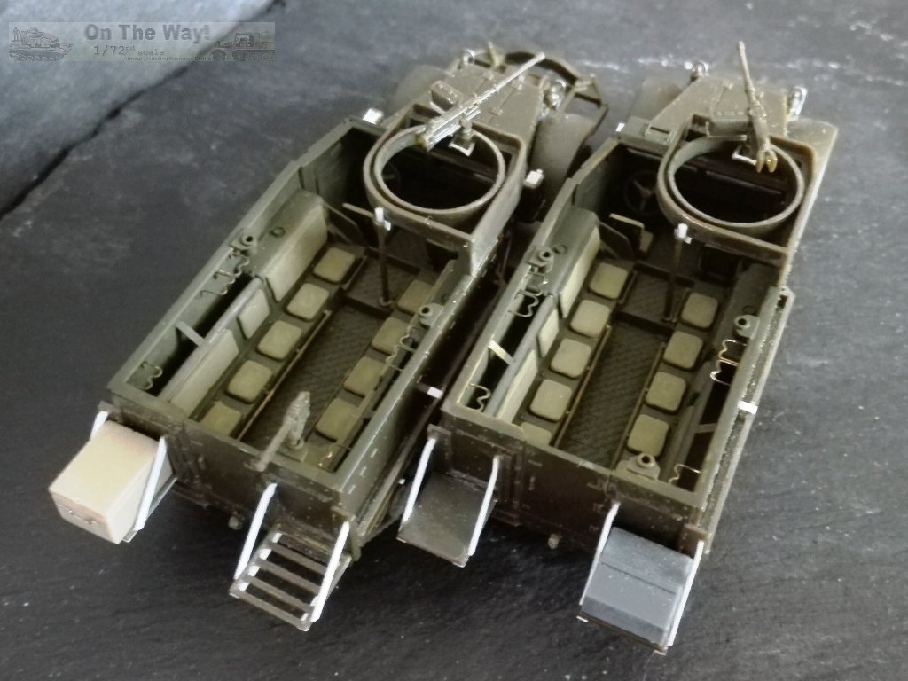
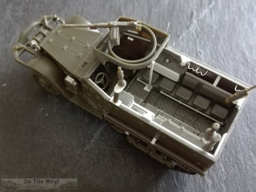
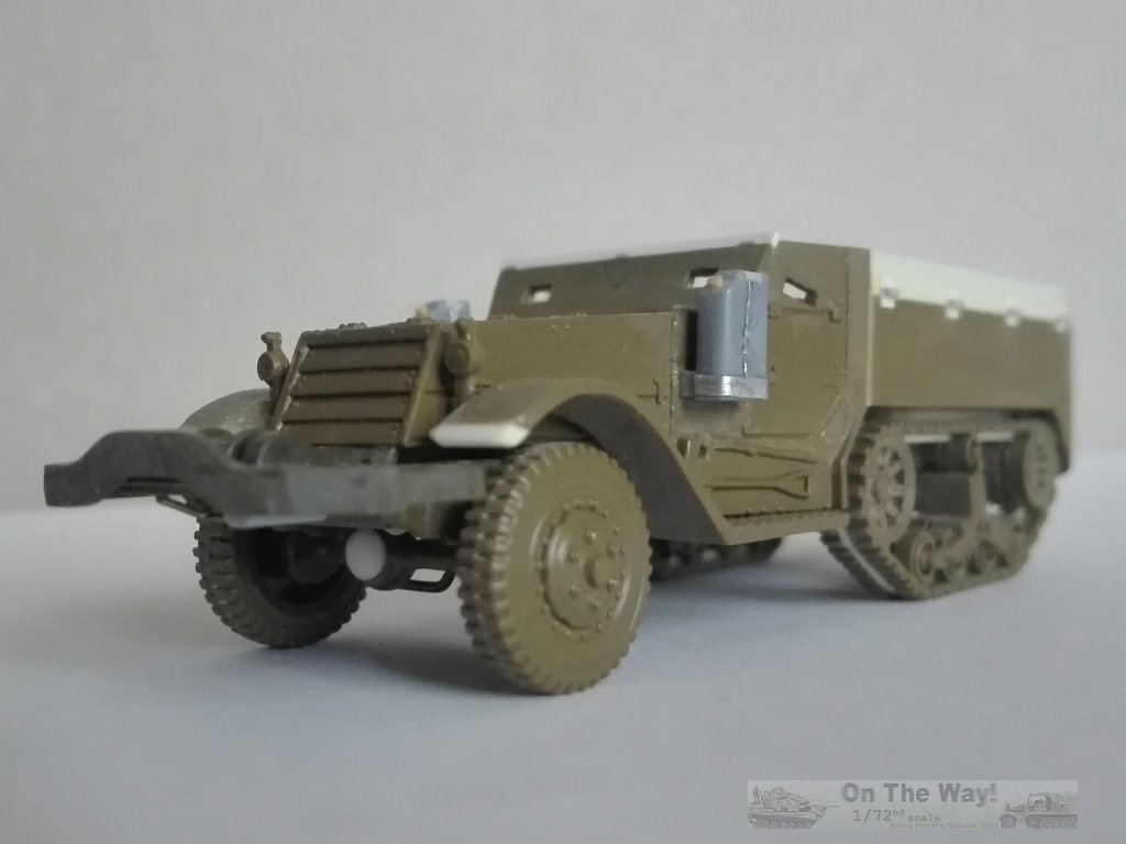
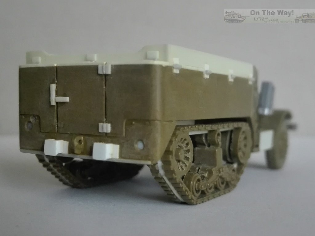
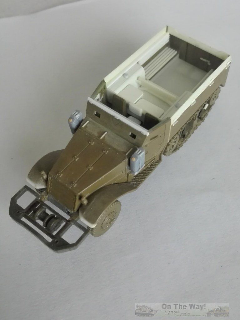
Measurements reveal that the Italeri kit is very close to 1/72, while Academy's is a bit wider (+1.2 mm; +1.7 mm w/ mine racks) and longer (+1.0 mm w/ roller; +0.5 mm w/ winch). FoV is a bit wider too (+1.5 mm; +1.7 mm w/ mine racks) and a bit shorter, apparently overall (-0.4 mm), but the crew compartment is 1 mm shorter and this produces a problem at the rear: a compressed look to the hook shock absorber and a smaller gap between the idler and mudguard. Quite surprisingly, the dimensions are the most accurate with Italeri's quick build kit. Before going on, a little note regarding the rifle racks. They are missing in every 1/72 kit. To make them in scale they would be very tiny, delicate and hard to depict. Nonetheless, they were there, immediately visible looking into the crew compartment. After a week of various attempts at making different templates and trying different materials, frustration led me to choose a solution which looked stronger and less bad to me, although doesn't leave me completely satisfied. Despite my dislike of photo-etch, this is a piece that should be available from an after market maker. One last thing about the racks: the rifles would be placed with the butt upward, possibly for added safety or to prevent something entering the barrel. So, now on to the models. Go to Academy review Go to Forces of Valor review Kit #: 7509 Italeri's quick build kit contains two models. A mid olive green single piece hull and a frame with just 13 pieces are what's used to make each half-track. An instruction sheet and decal set complete the kit. There are no transparent parts provided. In the middle of the hull floor there is a piece of sprue which stands proud and can damage the decal sheet, the instruction sheet, or both (as happened to one of my kits). The kit depicts an M3 APC, produced between January 1943 and August 1943, but the mine racks introduced in August 1942 are missing (see above). Anyway, the racks could be absent on ambulance half-tracks also on late production vehicles, see for example 4054891 and 4055085. As for the M25 gun mount, an interesting and possibly unique variation is found with the 66 Arm.Rgt., 2 Arm.Div. M3. Its individual bumper code was HQ-6 and it had the M25 mount placed in the middle of the hood. It also had the mine racks and the early headlamps. Another rare if not unique variation seen in photos was the installation of an M32 mount for trucks on an anonymous M3 command post which could be a pilot anyway (the photo didn't have the caption). For those wishing to make a more accurate display model, the kit needs some improvements. Chassis - Most of the floor between the footsteps was removed and replaced with plastic sheet to give depth and to replace some moulded on detail like the exhaust pipe and drive shaft. - The bottom of the front roller was filled with a plastic piece. - The two small hooks placed over the front bumper needed some reshaping by sandpaper to obtain the correct look. - I made drive belt pulleys from plastic sheet disks and stretched sprue. - I also added steering rods by shaped metal wire and stretched sprue. - I removed the moulded on axle present between the track wheel suspensions and I replaced it with a piece of stretched sprue. - The track tensioning springs are not well depicted. They should overhang externally the frame while they are moulded on and directly under it. In a moment of laziness I left them as they are. - The penultimate transversal rod was cut off and replaced by a new one aligned to the idler axle. - A small segment of stretched sprue with thin metal wire wrapped around it, along with a frame made from plastic rod, reproduced the towing hook shock absorber. - To detail the solid tracks, I used a saw to cut them along the moulding line separating the tracks and the wheels. Into the cut I inserted 1.0x0.5 mm plastic rod segments. - To improve the sprockets and the idlers I thinned their outer edge using a piece of sandpaper wrapped on a rounded rod. The real items were very complicated to depict in 1/72. If wished, they could be replaced by the Dan Taylor Modelworks upgrade set. - The exhaust pipe end was protected from excessive vibrations by a little plate, which I reproduced with plastic sheet. Interior - I engraved the hull's interior door lines. - Dry fitting revealed how shallow the rear compartment looked. To deepen it, I cut off the hull's central floor to allow piece number 2 to go through. The part which falls in the driving compartment was cut off and placed separately. - The shims below the tanks were filed off and their outer side shimmed with thin plastic sheet. This, and the former point above, allowed me to gain almost a millimetre, which doesn't sound like much, but now the gap above the tanks is 2.0 mm and there is more space for the hull's upper edge (see below). - The floor is missing the tread pattern and the raised part is a bit too long. I cut them off and used an Italeri M4A1 floor (each) to have the new sections, added under the walls for the longest part and between them for the raised one. This produced a shorter raised section, the tread pattern and more depth (if I now desired to open the rear door, the floor would be at the right level without any gaps). - Inside the front I added the windshield frame with plastic strips. - On the raised floor segment there was a pedestal mounted M25. The telescopic pedestal was a tube with a rounded base and three long triangular braces. Inside is a smaller tube that could be raised to the desired height. On top of that was the turning mount. Italeri makes it as a solid piece which comprise the .50 MG and the ammo box. I replaced the complete mount with plastic rod and thin plastic sheet. - The .50 MG is quite well depicted; the perforated cooling jacket and the barrel are a bit over scale but they have the handle. The firing handles and the right part of the fork really need to be reworked; plastic sheet and stretched sprue improved it. The ammo box is the smaller 50-round D40731 fixed type. I choose to replace it with the standard 100-round ammo box, placed on a D90078 shelf, all made with plastic. - The backrests lack the center support. I made them witha plastic strip segment. - I used stretched sprue segments and glue layers to make a lower edge of the padded backrest, which is missing because the solid piece is moulded from above. Because of the padded sides I had to keep the lower edge a bit below its correct position. Another option would be removing them and replacing with plastic sheet. - Between the seat rows there were the footrests. I made them with stretched sprue. - Along the upper edge there was an inverted "L" shaped rod. To replicate this, I glued a stretched sprue, sanded flush to make the horizontal part. - Under the new edge there were the rifle racks, which I've mentioned above. I made them from thin metal wire. - Just behind the driving compartment seats there were shaped plates. I made them with plastic sheet. - On the driver's side compartment floor, I added the scratch built gear levers after having drilled their holes. - Between the seats, the central foldable one was filed off because it was raised and didn't stand on the floor. I made it with plastic and stretched sprue. - I added the windshield using transparent sheet. Hull - Piece #10 has an ejector mark which interferes with its placement, making its removal required. I also engraved the lower edge of the folding armoured windscreen. - I removed the moulded on Jerry cans and replaced them with some taken from the Academy kit. The Italeri ones are too thin and placed incorrectly, parallel and adherent to the walls, and not to the longitudinal axis of the vehicle. They were kept in place by a holder and a belt. - The holes found on the bottom of the seats were closed with plastic. - On the bottom front I replaced the interlock with a plastic piece to simulate the radiator bottom. Another one was glued to make the sloped plate behind the roller. - The towing hook was drilled open. - I made my M3s with the later removable headlights. I filled the holes in the mudguards and glued the headlights to the radiator sides, after having made their supports from plastic strip. Earlier headlamps are easy to do anyway, as can be seen on my M3 75mm GMC. - The headlamps require brush guards. I made them using a shaped staple and plastic strip. - The forward edge of the mudguards should be straighter. I corrected them using a file and sandpaper. Decals Four half-tracks are depicted. 1) US Army 2 AD, 56 Inf.Rgt. Bumper codes for 2 AD, 56 Inf.Rgt. are not correct. The Infantry unit for the 2AD was the 41 Inf.Rgt. The 56 Inf.Rgt. was part of the 12AD. Both registration numbers - 40651400 and 40651428 - are one digit too long (see above list). If the last digit is truncated, the serial numbers could fall within an M3 batch. 2) Força Expedicionária Brasileira About their registration numbers - 40651460 and 40651465 - refer to above table. The only Brazilian M3 photos I've seen show them having the early headlight type, the mine racks and the national insignia as depicted by the set. They had US hood numbers, which unfortunately are not readable. No other markings are visible. 3) Free French 2eme DB. For both, the caption says 2eme DB, but the "drapeau consulaire" and the red background marking say 5eme DB, so the unit identification is not correct. - 430991, I couldn't find a supporting photo, but M3A1-half-track.com has a colour profile which depicts it as an M3A1 in Germany, 1945. - 652348, again no supporting photo was located, but it is depicted in the Peddinghaus Decals catalogue as an M3A1 in Germany, 1945. 4) British Army 64th A/T Rgt, 78 Inf. Div. As far as I know, just the M9, the M5 and the M14 officially served in the British Army. The only M3 variant used by the British was the 75mm GMC. - Z5805028, the WD number is out of the US half-track in British service, but... see below - Z5805037, the WD number is almost correct for Z5305037, an M14 in Italy. 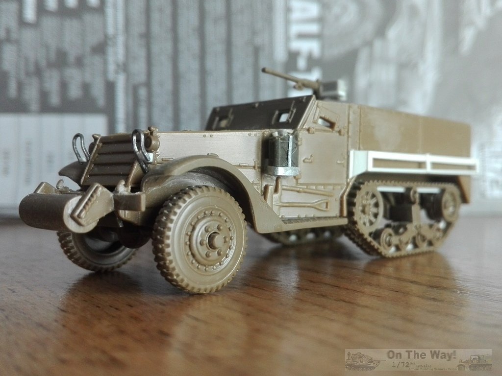
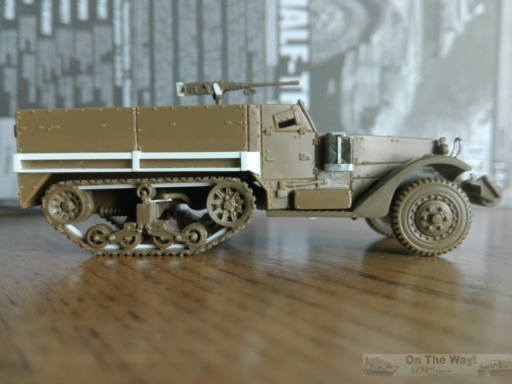
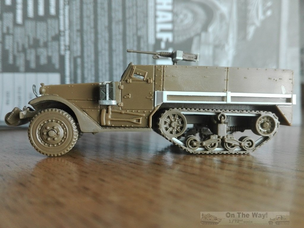
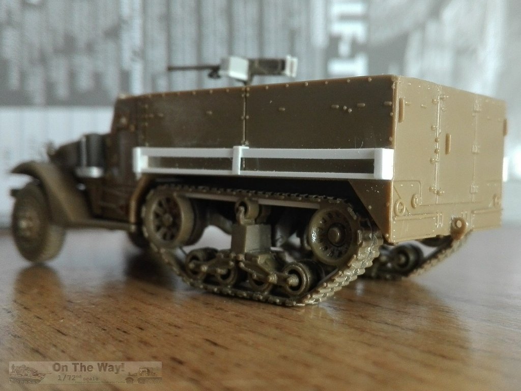

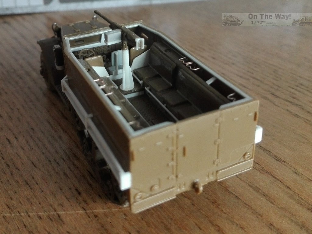
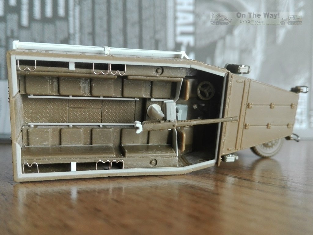
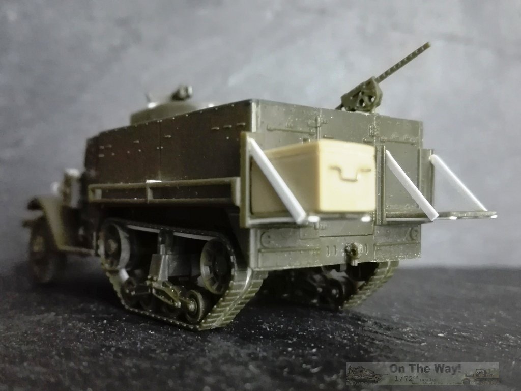
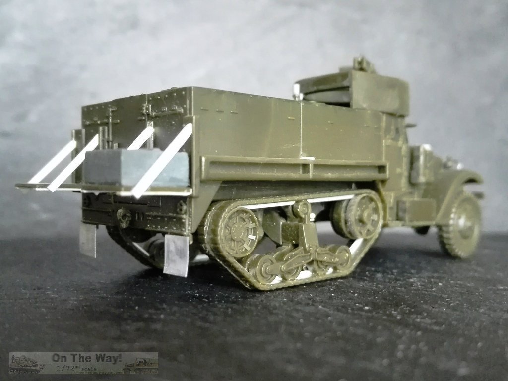
M3 ambulance For the second Italeri kit I chose to attempt an easy conversion to the ambulance variant. It was a standard M3 APC to which a simple modification allowed the transport of four stretchers. Surfing the web, I found poor info, however the Field Manual FM 8-35 gives generic info about the arrangement and also about the vehicles used as an ambulance. The manual also describes the stretcher types used (called litters in the text) and their dimensions. All stretchers (straight or foldable, were made from steel, aluminium or wood) were 90" long (1/72 = 31.7 mm) and 22 ⅞" wide, except the wooden type, which was 22" wide (1/72 = 8.1 and 7.8 mm respectively). All canvas beds were 72" long (1/72 = 25.0 mm). It also describes how they were placed on the vehicle. Two lay on the seats and two were suspended above them. The stretcher's inner rear handles were inserted in rings attached to chains fixed to the rear panel and the forward ones were supported by a simple structure welded to the M25 mount. The upper stretchers' outer sides fit into "U" supports welded to the hull. The photos I've found are few and poorly detailed; anyway, they were barely sufficient to shape the needed pieces crossing the images. On a very early ambulance pair (409455 and 409457) there was also a cage fixed on rear door inside and two bins replaced the left backrest. I added the required details to an unarmed M3 using plastic strips, metal sheet and wire. The stretchers, when not in use, were stored rolled, tied together and fastened over the backrests or hanging on the hull side (as I'll do in my case). Some first aid kits and blankets will complete the medical equipment. 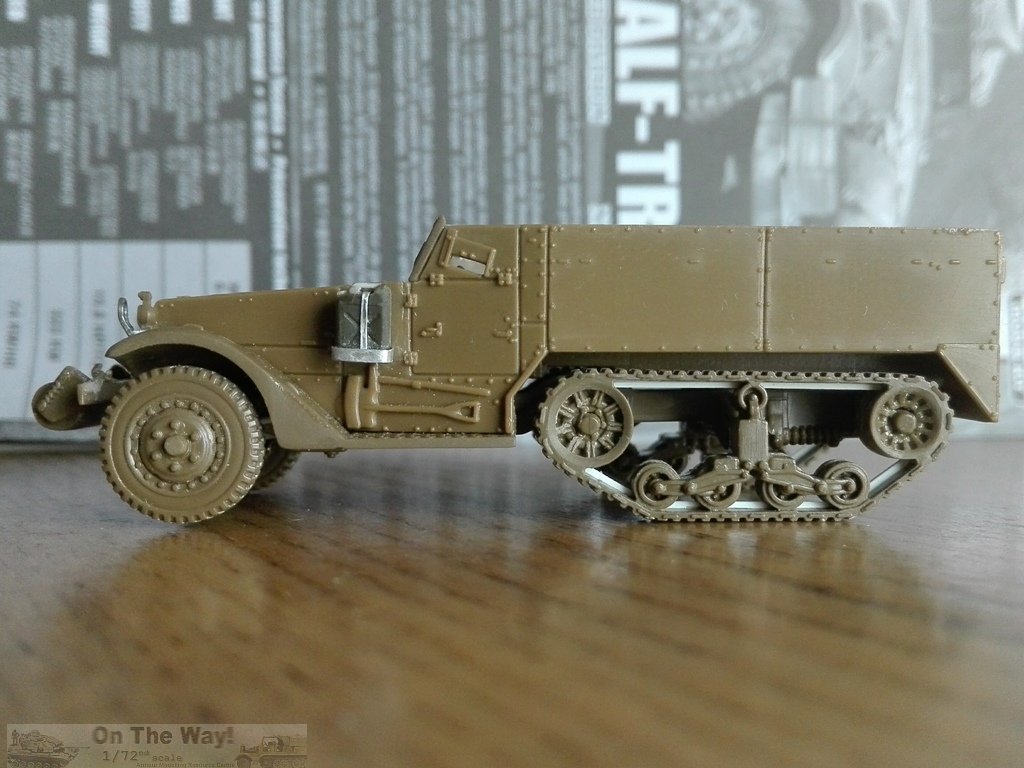
Kit #s: 13408 and 72013 The box and the instructions say the variant depicted is an M3, but the elongated M49 gun mount tells us it is an M3A2, the single prototype of a variant that was never produced. Don't panic, the conversion to a M3A1 is one of the easiest I've ever done. Academy's kit is composed of two dark olive-green plastic moulds. One has the generic parts, common to other half-track variants; the other has pieces more strictly connected to the M3A1/A2. Although this leaves one with the impression that other variants would follow, none were produced by Academy until now. A lot of tiny pieces and crisp details are given, and despite my former experiences with other Academy kits, this looks to be is a well-done model. No transparencies are given. The instructions and the decal set complete the kit. My boxing also had the Ford GPA and the Harley Davidson motorbike, but a stand alone kit is also available (kit # 72013). A couple of nice bonuses are given in the form of two Jerry cans plus a .30 MG. Optional parts give the choice between a roller and a winch. Chassis - The upper part of the engine front is cut too low. It ends before touching the plate which makes a floor between the mudguards leaving an ugly empty space. I shortened the "floor" to have the lower part of the radiator and added a plastic piece over the lower half of the distribution belt. After having shaped it, I added a couple of pulleys to have a more realistic look (the third wouldn't be visible as well as the fan). - The spring leaf suspension, parts A20 and A21, are nicely moulded, but when placed as directed, the pins don't match the holes on the axle, part A12. Furthermore, the drive shaft interferes with a part of the engine, and the steering transversal rod touches the sloped belly, which pushes the axle a bit forward. To position the axle correctly, I removed the spring pins and I shimmed them. I cut a thin notch on the engine side on the drive shaft insertion point, in this way the axle went in the desired position. Before gluing the axle I had to reshape the bent part of the transversal steering rod, which is solid. - The kit provides two options: roller or winch. The roller is missing its small lateral springs. I made them using very thin metal wire wrapped around thin stretched sprue. Academy forgot to make the winch's lower gear case, and its drive shaft, which should go through the hole present in piece # A4/A5. I fashioned both from plastic and stretched sprue, and I had to cut off and glue separately the plate present under the radiator louvers, for my half-track with the winch. I also added the winch brush guard fashioned from metal wire. - To detail the solid tracks, I used a saw to cut them along the moulding line, separating the tracks and the wheels. Into the cut I inserted a plastic rod. - The rear end of the chassis has the two transversal rods incorrectly placed. The outer one is pushed inside and the inner one doe not align to the idler's axle. I cut both and placed them in the correct position. In between them, I made the towing hook shock absorber with a section of plastic strip, stretched sprue and metal wire. - The exhaust pipe end, A17, doesn't depict the correct shape. I replaced it with metal wire, and it received its little plate, made with plastic sheet glued to the suspension (see above). Interior - I engraved interior doors lines in the driving compartment. - If placed as suggested, the steering wheel will be shifted outward and will not be aligned with the centre of the driver seat. I glued it paying attention to the correct position. - The backrests had a central support. I made them with a plastic strip segment. - Under the new edge I added rifles racks made by thin metal wire. - I used stretched sprue segments glued in layers to give a lower edge to the padded backrest, which is missing because the solid piece is moulded from above. Here too, the option would be erasing them and replace with plastic sheet. - The .30 MG's support bases received a shim of thin plastic strip. - I added the windshield from transparent sheet. Hull - There is a small discrepancy in width between the driving compartment (28.2 mm wide) and the fighting compartment (29.1 mm wide), leaving a 0.4/0.5 mm step between the two parts. I realized this too late to fix, though the issue should be easily resolved by narrowing the floor, part B1 and the rear plate, part B12. - The rectangular holes under the tanks were filled with plastic pieces. - The luggage rack's folding parts, B13 and B14, are molded solid, but they should be frames. On one of them I opened the spaces between the frame rods. The underside received the other side of the L rods which keep the frame together. Not an easy job. A complete rebuilding with plastic strips is probably easier. On the other shelves I used another approach. I glued them upside down. The frame is visible from below, while the top is hidden by the stored items. It's easy, and it works. The shelves had their supports made with plastic strip sections. - The armoured windshield is nicely moulded as two pieces (A31 and A32) so it can be depicted either closed or opened. If depicted closed, the thickness of the pieces will produce a nasty step where the two pieces are hinged, instead of being flush. For the half-track I made, with the armoured windshield closed, I cut off the windshield frame and glued piece A31 to the upper rod and then glued the frame inside. On the one I made with the armoured windshield opened, I added the three missing supports from thin stretched sprue. Despite their locations being symmetrical on piece A31, they weren't. The correct locations are moulded on the bonnet. - The forward edge of the mudguards should be straight, I corrected them with files and sandpaper. - The M49 mount depicts the variant adopted for the M3A2. I cut off the excess for my M3A1. The MG mount had its handle made from stretched sprue. The little bulge on the curved side was removed. It was replaced with a small plastic sheet rectangle, to which the support pole was fixed externally. For a better placement, the support (part B7) was glued to the M49 mount (B2), and then the sub-assembly to the hull. The overhanging part over the door needs to be closed. A little shaped piece of thin plastic sheet filled the slot. - The .50 MG handles were detailed using a file and a sharp blade. The otherwise fantastic ammo box has a sink on both sides! Filling them meant losing the lateral details, but leaving the sink marks is even worse, so I filled them with cyanoacrylate glue and sanded down the sides (I was disappointed by this). Then I filed 0.5 mm from its bottom and used plastic strip for the bracket. - The .30 MG's are very fine but lack the ammo case. Because of the small scale, the M1917A1 cradles are moulded solid. To give a personal touch, I drilled the cradles and replaced the pintle. This allowed me to give it a different angle other than dead level. - The track's thick splash guards were replaced with thin metal sheet which can be bent for a more realistic look. - The Jerry cans are quite well done, but their section is a bit too square, so I rounded them. The handles and the caps were replaced with stretched sprue. - The headlamps are missing their brush guards. I made them from a shaped staple and plastic strip. Decals Two US half-tracks are depicted, neither of which I could verify with photos. 1) 403775S, 1AD 6 Inf. Rgt. The registration number matches an early M3 batch. 2) 403763S, 5AD 27 Inf.Btn., for the registration number see above. About the bumper code, the 5 AD infantry units were the 15, 46 and 47 Inf.Btn. The 27 Infantry Regiment was part of the 25 Inf.Div. based in the PTO. About both bumper codes, the marking for the Infantry unit (Regiment or Battalion) is the letter "I" divided by a dash from the unit number, and not the number 1 as incorrectly printed on the set. 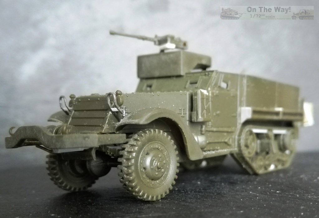
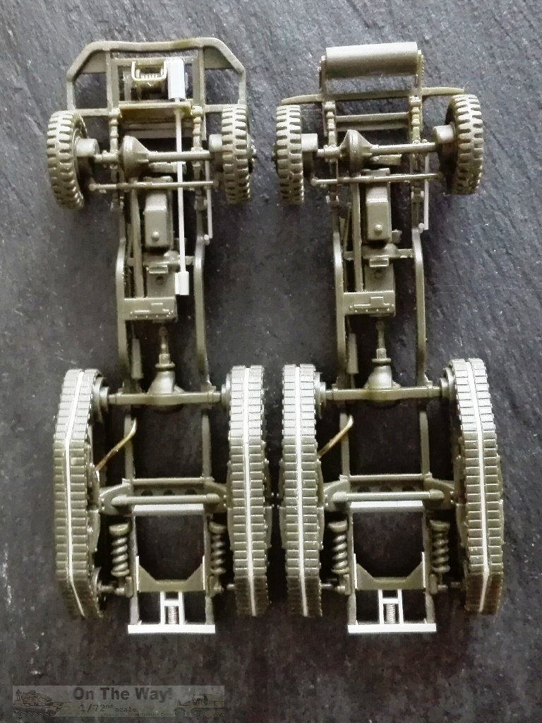
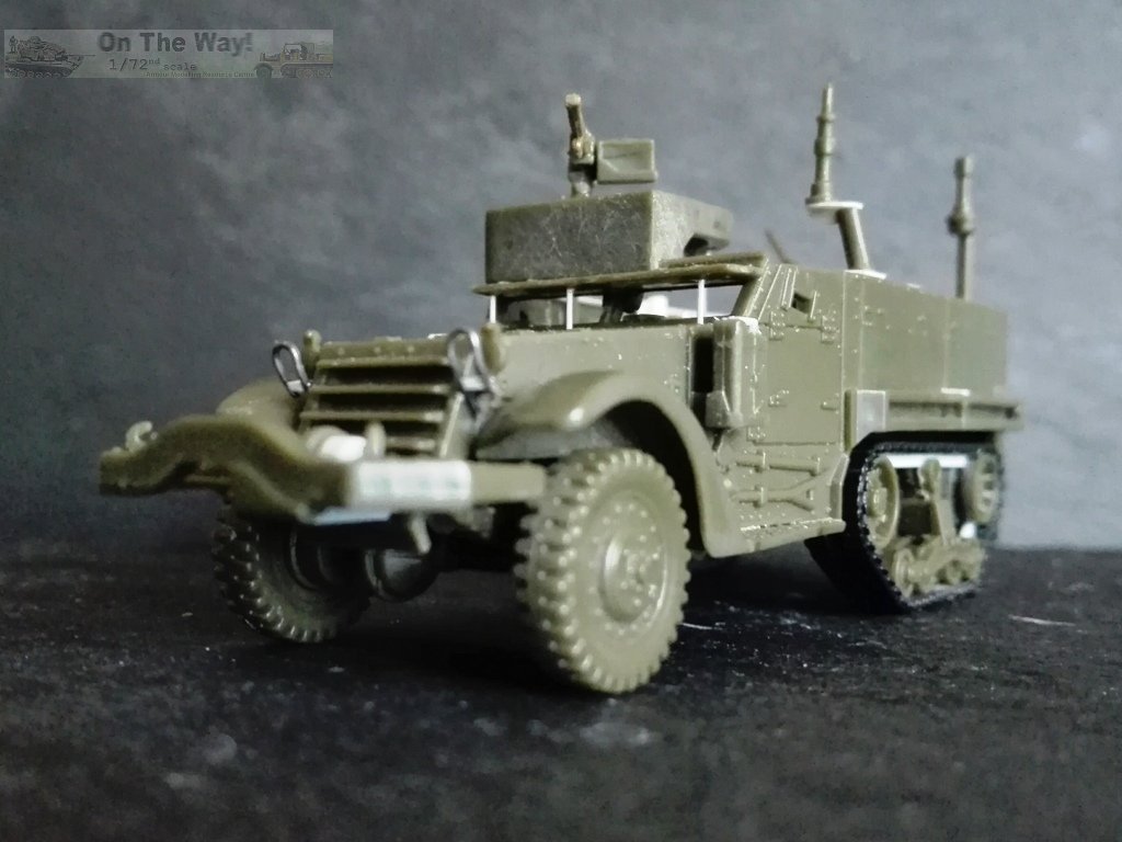
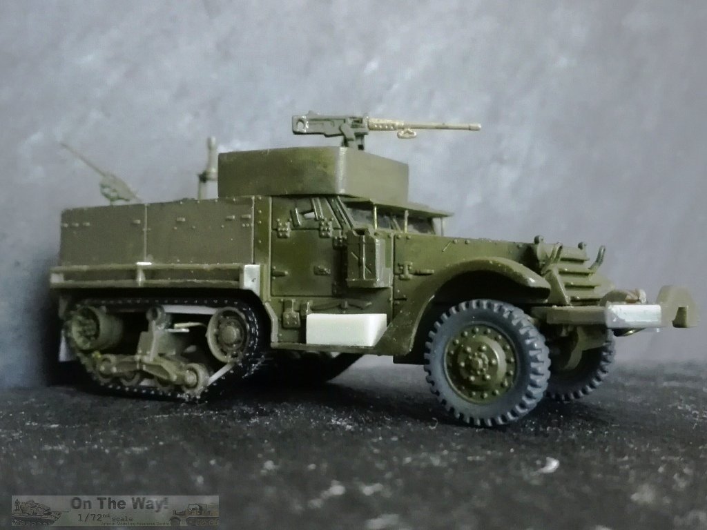
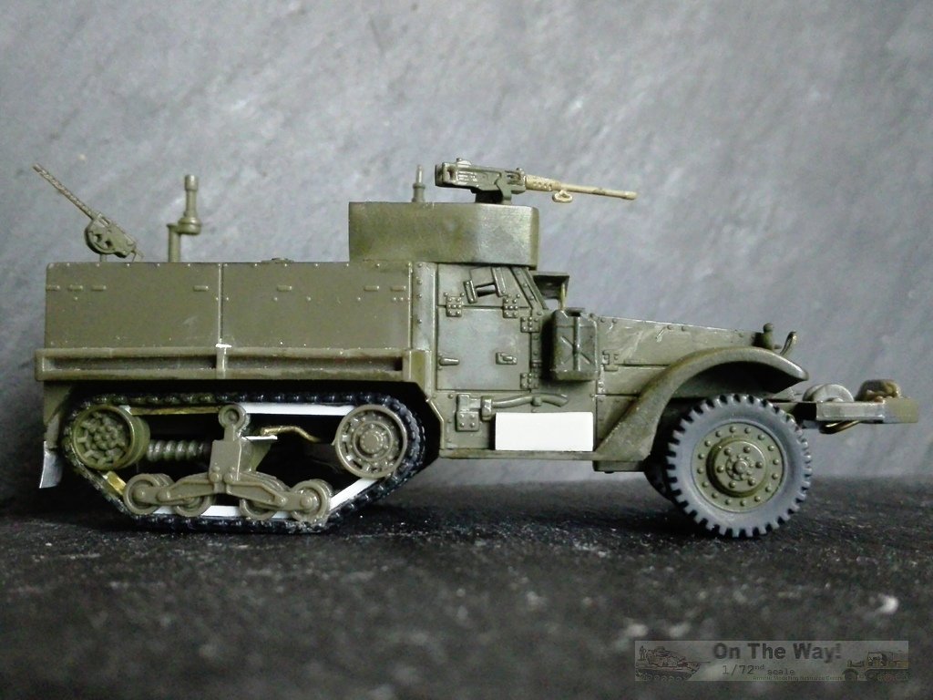
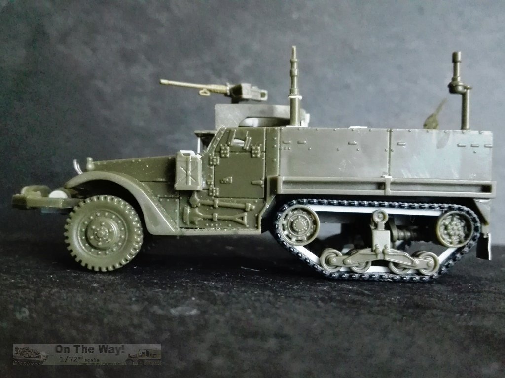
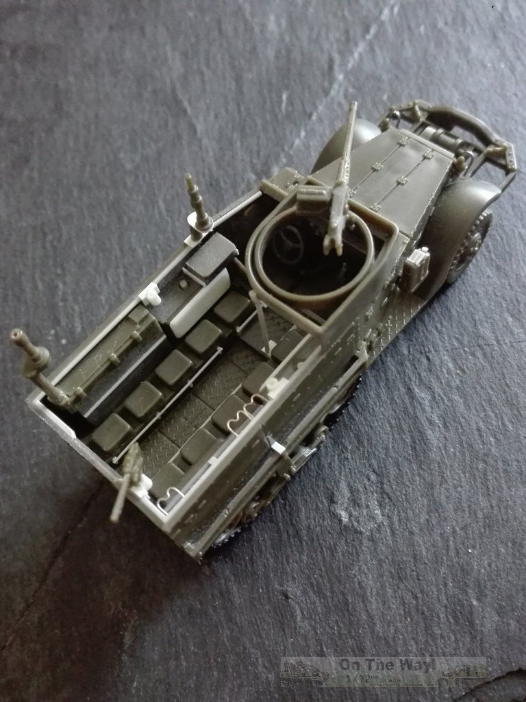
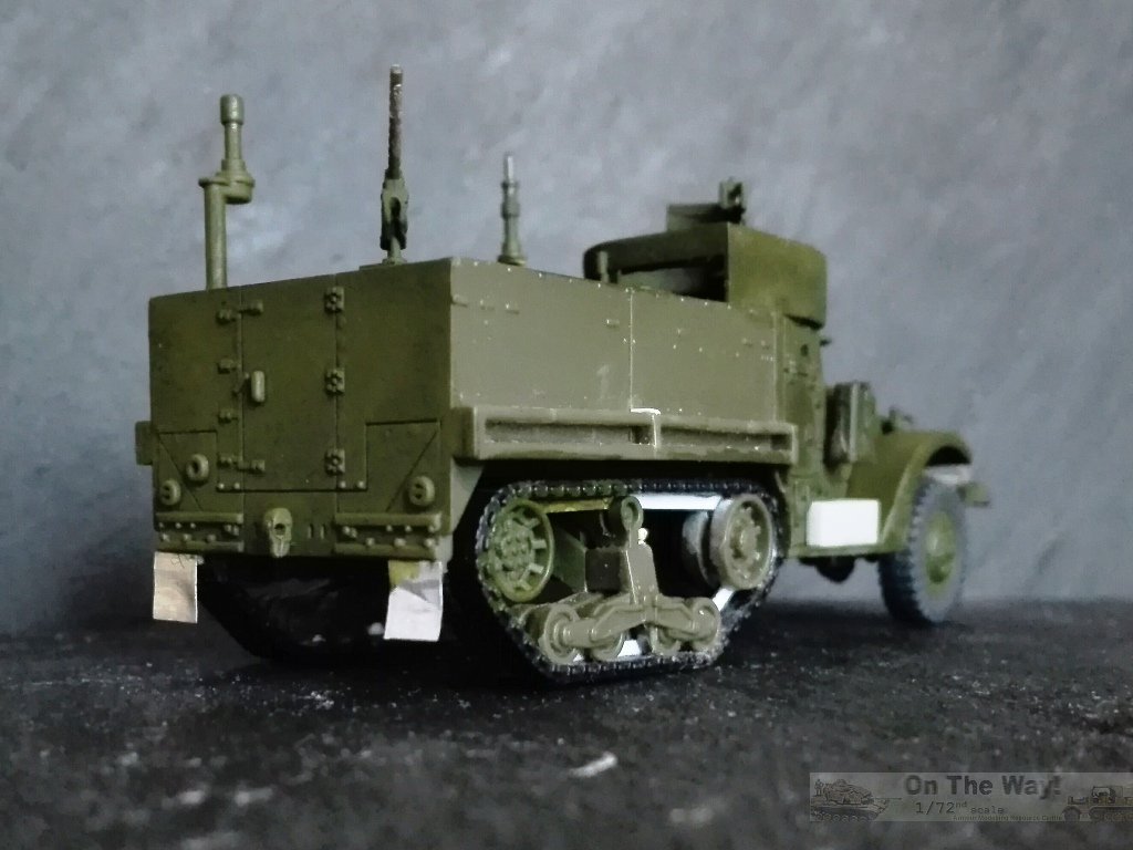
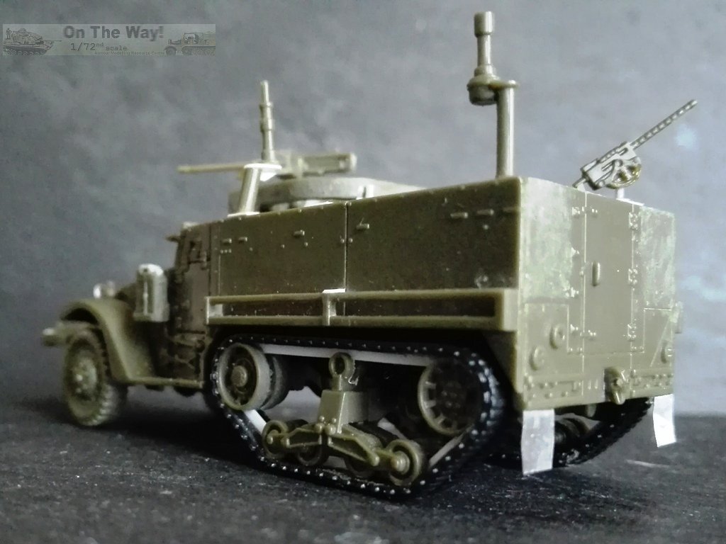
Waltersons kit #: 873007 The Forces of Valor kit is comprised of two dark olive-green moulds containing the smaller pieces, two single pieces for the hull and the chassis, and a black rubber moulding with the tracks and driver. Each one is separately packaged in its own transparent envelope. Instruction and the decal set complete the kit. Oddly, the instructions say the model depicts a 46th Inf.Btn. 5th AD, but the decals are for a 41st Inf.Btn 2nd AD. The variant depicted is a headquarter M3A1, which could have different radio apparatus. As far as I've found, radio equipment at least included the following types: SCR-193, 245, 506, 508/528, 510. Although the suggested layout has the smallest radio over the right backrest as being correct, I chose to modify it. The layout I chose has the large cabinet replacing the left backrest and the second smallest radio over the left tank. A similar layout can be seen on the Flying Heritage and Combat Armor Museum half-track, 40150367, which however is an ex-M15A1 restored as an M3A1 HQ, and on privately owned 4044090, a veteran M3 upgraded to M3A1 in 1944. A close observation reveals how a few details look exaggerated such as some riveting, and some problems were found during assembly. Measurements tell us it is a bit wider, like the Academy kit. Unfortunately, big problems arose (to me) about the chassis, which is incorrectly shaped around the sprocket's axle, and the driving compartment, which is much too deep. These issues required a deep intervention which didn't completely solve the problems. In the end I had to cut the chassis into two halves. Chassis - As written above, the frame is incorrect at the sprocket level, where the profile is not respected. I wanted to correct it, but all attempts to keep the frame as a single piece didn't work because of the modified chassis' weakness, so when all was said, I choose to keep the two halves separate. On the forward half I glued the floor,part A12 (see hull section), and then reshaped the frame to a more correct profile. If one makes this kit to be attached to a base the problem is barely, if at all, visible and all this grief can be spared. - The winch's frame thickness is a bit exaggerated, so it was thinned using a file. - To the chassis I glued the lower portion of piece A4. When dry, I opened the hole for the winch drive shaft, which was fashioned from plastic and stretched sprue. - To the winch I had to add the gear case made from shaped plastic (over and under the frame), the drive shaft, plus a winch brush guard from metal wire. - I had to reshape the bent part of the transversal steering rod, which is solid. I added also the rod coming from the rear part of the steering system. - I made the drive belt pulleys with plastic sheet disks and stretched sprue. - The solid return roller was divided using a saw and the suspension/chassis interlocks filed a little to get them correctly aligned with the sprockets and the idlers. - The track system is not very well done. It stands a bit outside and the alignment is not correct. The 12" tracks (1/72 = 4.2 mm) are over sized, being 4.5 mm wide, and when measured at the pitch pins, becomes 5.4 mm. Outside they have the groove, but inside there are teeth instead of the rail (again!). Other negative points are the thickness and the rigidity of the black rubber, which tended to take on a domed profile when placed on the suspension. I wasn't satisfied with the look, so to improve the things I removed the guide teeth with a sharp blade. I then glued plastic strip segments to make the track rail directly on the suspension. This also provided rigidity. When dry, I added the tracks, gluing them to the wheels and the rails with cyanoacrylate. In this way the tracks look tensioned as on a real vehicle. - The rear end of the chassis has just a transversal rod and it is placed incorrectly. I cut it off and glued it aligned to the idler's axle. The last was made by a plastic strip segment to have a half of it because the hull rear plate lower edge thickness was left intact. Between them I made the towing hook shock absorber using a plastic strip section, stretched sprue and metal wire. - I added the last segment of the exhaust pipe from metal wire, which received its little plate, made with plastic sheet. Interior - I removed the moulded .30 MG supports because their positions were too high. I replaced them with plastic strip segments. I also added the rear one, missing in the kit. - The larger radio cabinet, part A7 was modified. The locks were shortened, and the hinge was added with stretched sprue. The antenna mast, part B14, was glued on the cabinet's side and its hull interlock filled. To keep the correct position, the antenna mast was cut and glued turned. - The smallest cabinet was cut off from the backrest (part A8), which was reshaped, and its deepness corrected. The radio cabinet was placed behind the driver with two plastic strips for the mount (the original FM48 mount was a bit more elaborated, I know). The antenna mast was modified as seen in photos and placed close to the cabinet. I had to add a little triangle under the shelf because of its weakness. - The padded backrests attached to the tanks are almost nonexistent. I made them with plastic sheet. - I made footrests from stretched sprue. - Only on the side without the radio apparatus, I added rifles racks made from thin metal wire. - I added the windshield using transparent sheet. Hull - The first thing I did was to remove the name of the kit found on the hull's belly! - The tanks underneath are open. I closed them with plastic pieces. - I engraved the interior door lines. - The rear plate's thickness is huge. I thinned the upper half before gluing it in place to avoid a unlikely door thickness at the end. On the outer side I sanded down the huge rivets. I also removed the moulded on handles, which were replaced with metal wire. - Piece A12 has the driving compartment floor and the mudguards. Dry fitting revealed the floor was much too deep and when placed, the chassis doesn't completely touch the hull in the engine area. After some attempts, I choose to cut off the floor and glue in place just the mudguards. The floor was glued to the chassis to solve the chassis problem. - I corrected the mudguards' edge shape with sandpaper after referring to photos. - The battery box is missing. To make it, I shaped a piece of resin sprue. - The lower part of piece A4 was cut off and glued to the chassis. - The M49 mount is correctly depicted. I cut off the lateral interlock because I had modified the hull's side thickness. The only improvement I made was to thin down the rear vertical edge thickness. The little bulge on the curved side was removed. Its place was taken by a small plastic sheet rectangle, to which the support pole was fixed externally. This also meant a new lower placement to keep it vertical. The overhanging part over the door needed to be closed. A little shaped piece of thin plastic sheet filled the slot. - The .50 MG needs some care. I replaced the barrel by an unused Italeri one. The handles were detailed using a file and a sharp blade. - The .30 MG's are as good as the Academy versions, so I replaced the lonely used by one of them. - The thick splash guards were replaced with thin metal sheet, which can be bent for a more realistic look. - The mine racks had their mid-length supports made with plastic strips. - The Jerry cans are quite well done, but their section is a bit too squared. I rounded them. The handles and the caps were replaced by thin stretched sprue section. - The headlamps should have brush guards. I made them from a shaped staple and plastic strip. Decals I didn't find the photo of the only vehicle depicted: 1) 40202907, 2 AD 41 Inf.Btn. The hood number is too high to match the known list. Regarding both bumper codes: the marking for an Infantry unit (Regiment or Battalion) is the letter I separated by a dash from the unit number, and not the number 1 as incorrectly printed on the sheet. 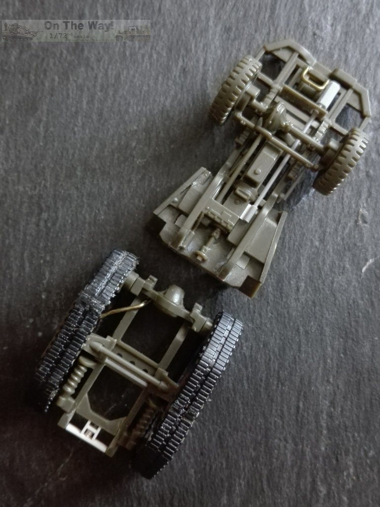
Inbox notes: Hasegawa kit # 31106/MT6 I have not purchased this kit. A friend let me have a look at their unassembled kit so I could make some observations about it. The photo taken from the catalogue immediately reveals some of this kit's faults. Without going crazy on smaller detail issues, I'll point out the major flaws as follows (see photo below): 1) Early wheels (used only on early M3s) are incorrectly depicted by Hasegawa as having five holes. The original real wheels had six holes. 2) Early fender headlights are only correct for an M3 upgraded to an M3A1. 3) The doors are smaller and have a non-existent frame on the upper and forward side. 4) The side walls are too short. They should run level from the windscreen back to the rear panel. This means the rear panel is too short as well. (See yellow line in below photo.) Other macroscopic faults lay in the flat floor and the poorly detailed chassis. What is not obvious in the photo is its size. Using my Mk.I eyeball while the pieces were still on the sprue, the dimensions look over sized compared with the Academy kit. I estimate the scale to be a bit larger than 1/72. Because the Hasegawa M4A1 half-track (kit # 31107/MT7) shares two out of three 31106/MT6 kit sprue frames I can assume they also share the same size error. 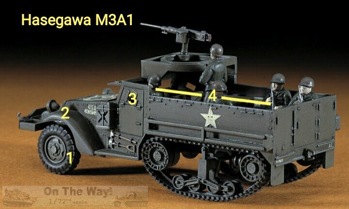
Conclusion Italeri gives us an honest model and it is the most correct dimensionally. It's simplicity is aimed at the war gaming crowd, but it is correct and detailed enough to be converted into a display model. If I had been the designer, I'd improve it with a deeper interior (with a non-skid floor) and reshape the bonnet's Jerry cans. A nice touch would have been the presence of mine racks. However, it is still a good base to work from. The Academy kit makes into a decent display model, despite some details being oddly missing or incorrect. Most disturbing is the width difference between the driving and crew compartments, over that of its over sized width. The way it is moulded suggested the possibility of a full line of variants being released, but currently there has been no trace of other kits based on it. The Forces of Valor M3A1 is a strange kit. It can look generally quite well done ,although not extremely detailed, if one can ignore the ugly chassis and driving compartment mistakes. Furthermore, it has an assembly problem which leaves, if not resolved, a wrong look in the forward area. On the other hand, it suggests a variant not depicted by the other brands making it interesting to build. Hasegawa doesn't hold a candle to the others regarding dimensions and accuracy, but for decades it was the only one on the market. It could be detailed using specific after market items, an option which make no sense with other manufacturer options now being available. Every kit of this comparison needs the revision to its decals. So with all that said, there is no real winner, and if it's strongly desired to build a "definitive" half-track, one has to use more than a single kit, taking the best or the required parts from different kits. In my opinion the "US half-track" is an underrepresented vehicle in the 1/72 world. It wasn't used solely by the US Army, but also served post-WW2 in other armies. Even the Germans employed some captured ones. Clearly this provides numerous modelling possibilities. Despite this, while the market is full of Sd.Kfz.251 kits (its German counterpart) in almost every variant, strangely enough there are just three useful M3 kits, which depict just a sole variant, the M3/M3A1 plus a fourth for the GMC M3. Currently other variants can only be depicted via conversion. Plastic sheet and rod are needed to make something different. To show what I mean I've attached some photos (see below) of a British M14 truck (15cwt) I've converted using the second kit from the Italeri 75mm GMC. There is still room for kit manufacturers to produce other variants. 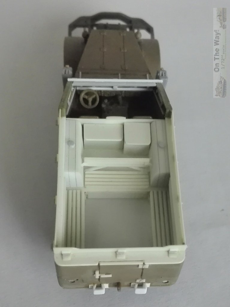
Review samples purchased by the author. Italeri
products are available at
|
|||||||||||||||||||||||||||||||||||||||||||||||||||||||||||||||||||||||||||||||||||||||||||||||||||||||||||||||||||||||||||||||||||||||||||||||||||||||||||||||||||||||||||||||||||||||||||||||||||||||||||||||||||||||||||||||||||||||||||||||||||||||||||||||||||||||||||||||||||||||||||||||||||||||||||
| Back to Academy List Italeri List Forces of Valour List |
Back to Construction Reviews |
Article Last Updated: 20 December 2020 |
Back to Home Page |