|
Pit-Road
|
IJA 28cm Howitzer |
|||
| Kit #: SG04 |
Review by
- Al Magnus
|
|||
|
Pit-Road
|
IJA 28cm Howitzer |
|||
| Kit #: SG04 |
Review by
- Al Magnus
|
|||
 |
|
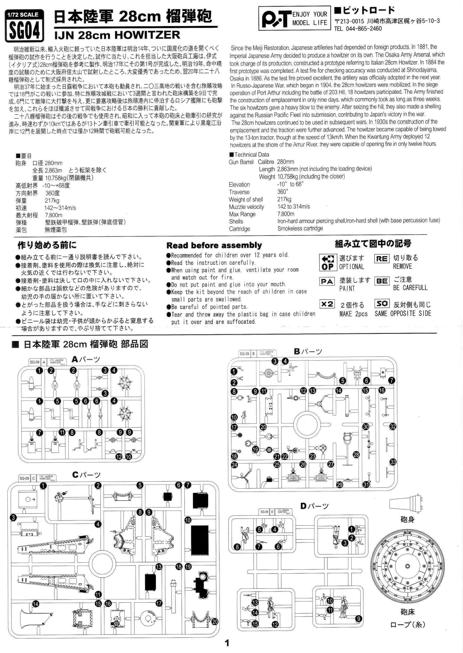
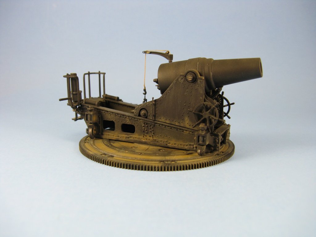
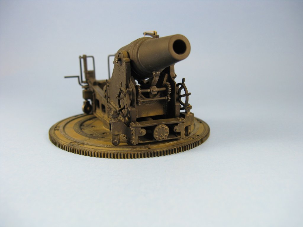
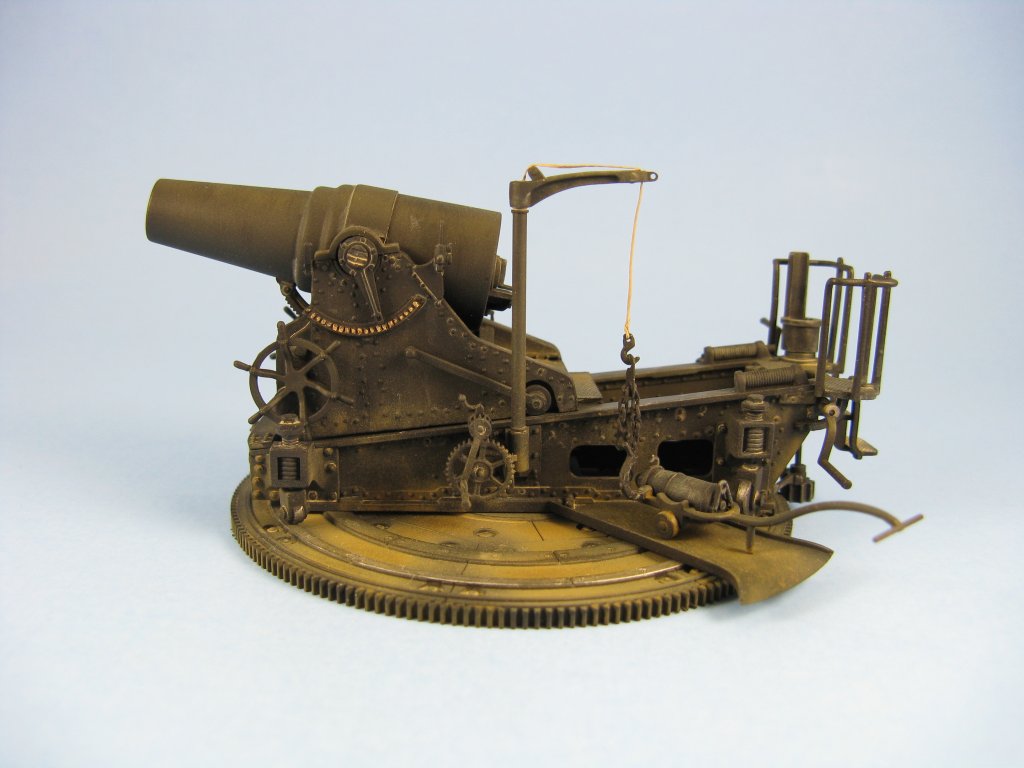
History The 28cm (11 inch) IJA howitzer was built by the Osaka Army Arsenal, patterned on an Italian gun designed for them by the British. The gun was officially adopted for production in 1887. It was used against Russia during the Russo-Japanese War just after the turn of the 20th century. In late 1904, six of the guns were used in the capture of Hill 203, and then employed in the siege of Port Arthur in Manchuria. Over the course of the next few months the howitzers were used to devastating effect on the Port itself, as well as sinking four battleships, a pair of cruisers, and damaging one more battleship, and in early 1905 the Russians surrendered after most of their Pacific Fleet had been destroyed. The guns were also used again during World War One. At this time Russia and Japan were allied against Germany, and Japan provided some howitzers to Tsarist Russia, some of which were captured by the Germans during the course of the war. During the 1930s the guns were modified for towing by a 13-ton tractor, and subsequently used again against Russian forces at the Amur River in what was to be the beginning of the Khalkhin Gol/Nomonhan War. The howitzers also appear to have been in place as coastal defence around Tokyo Bay and Western Japan during World War Two. The kit The build Construction was straight forward, requiring few deviations from the build sequence. The modular design of the real gun as well
as for the kit makes it easy to build the model a separate subassemblies which can be painted and then put together at the end. Parts fit, which is
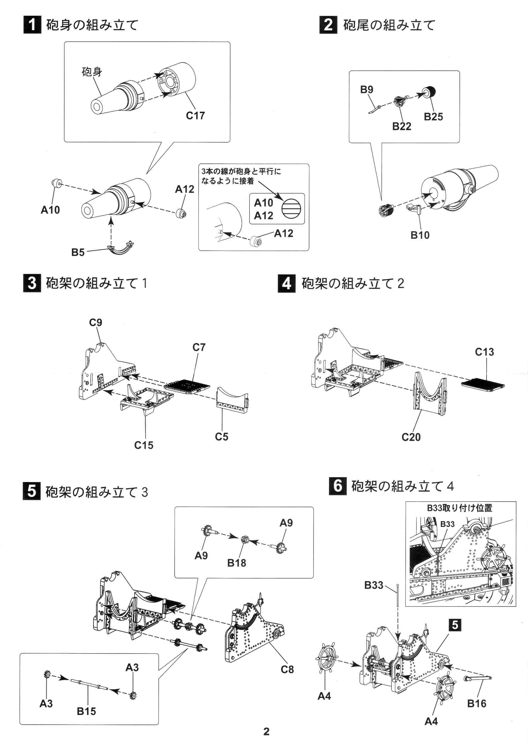
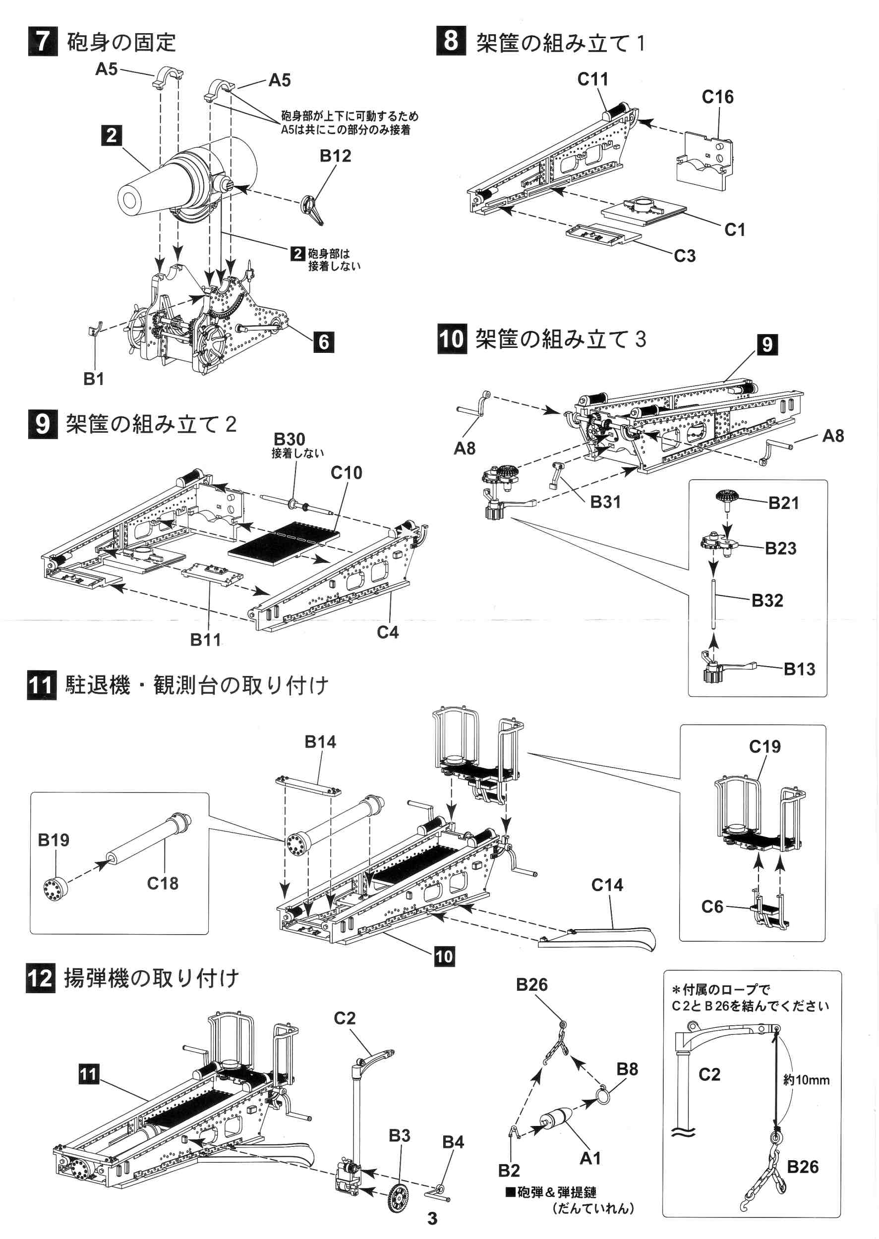
exemplary throughout, is not an issue with this kit making assembly a breeze, though there are a few points to note. Instructions don't really show it but the gears (parts A3/B15/A3 and A9/B18/A9) in Step 5 will need to mesh together when mounted in the carriage. In Step 10 I found it easier to add the parts individually to the carriage instead of trying to put everything together first
and then trying to fit the assembly into place, that is, glue B31 then B13 to the carriage, then glue B21 to B23, then add the shaft B32 (which I replaced with
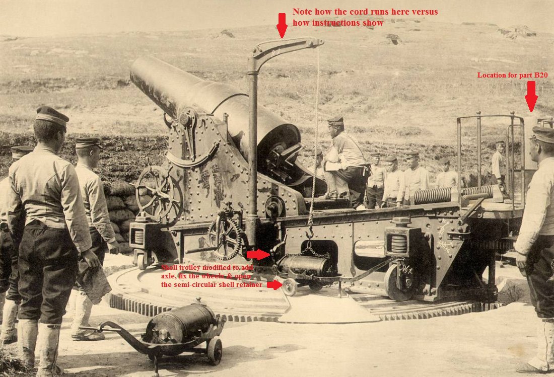
a piece of plastic rod cut to size), and finally slide the B21/B23/B32 assembly into place making sure that gear part B21 meshes with B30 added in Step 9. When adding part C14 in Step 11 temporarily join the carriage to the turntable before gluing the part in place. This will ensure that it sits level. At Step 12 I made my only major deviation from the instructions. First was the crane (part C2) which I modified based on my reference photos.
A hole was drilled in the top of the vertical shaft, and another smaller hole at the tip just behind the loop. Photos show that the cord does not attach to the loop on the
end of the crane's arm, as shown in the instructions, but instead passes through a hole in the arm just in front of another pulley. I did not use the thread provided for the hoist. I've always found thread to be too furry for use as cable. Instead I used some braided fishing line.
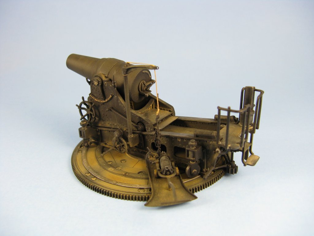
The kit's chain (part B26) is moulded so it can be attached to the front (part B8) and rear (part B2) mounts glued to the shell in Step 12 but
I wanted the chain to hang loose and have the trolley displayed with a shell in place and ready to be hoisted, so I substituted some metal chain for the
plastic version in the kit, and went to my spares box to replace the two hooks found moulded on the kit's chain. One hook was super glued to one end of the metal
chain and the other was twisted onto the end of the fishing line. The new cable and chain were not attached to the crane until final assembly following painting. I also modified the shell trolley by cutting off the moulded on wheels and added new ones punched from a plastic sheet. The an axle
is missing so it was added as well with a short section of plastic rod. At the front of the trolley I cut off the semi-circular brace so I could mount it in
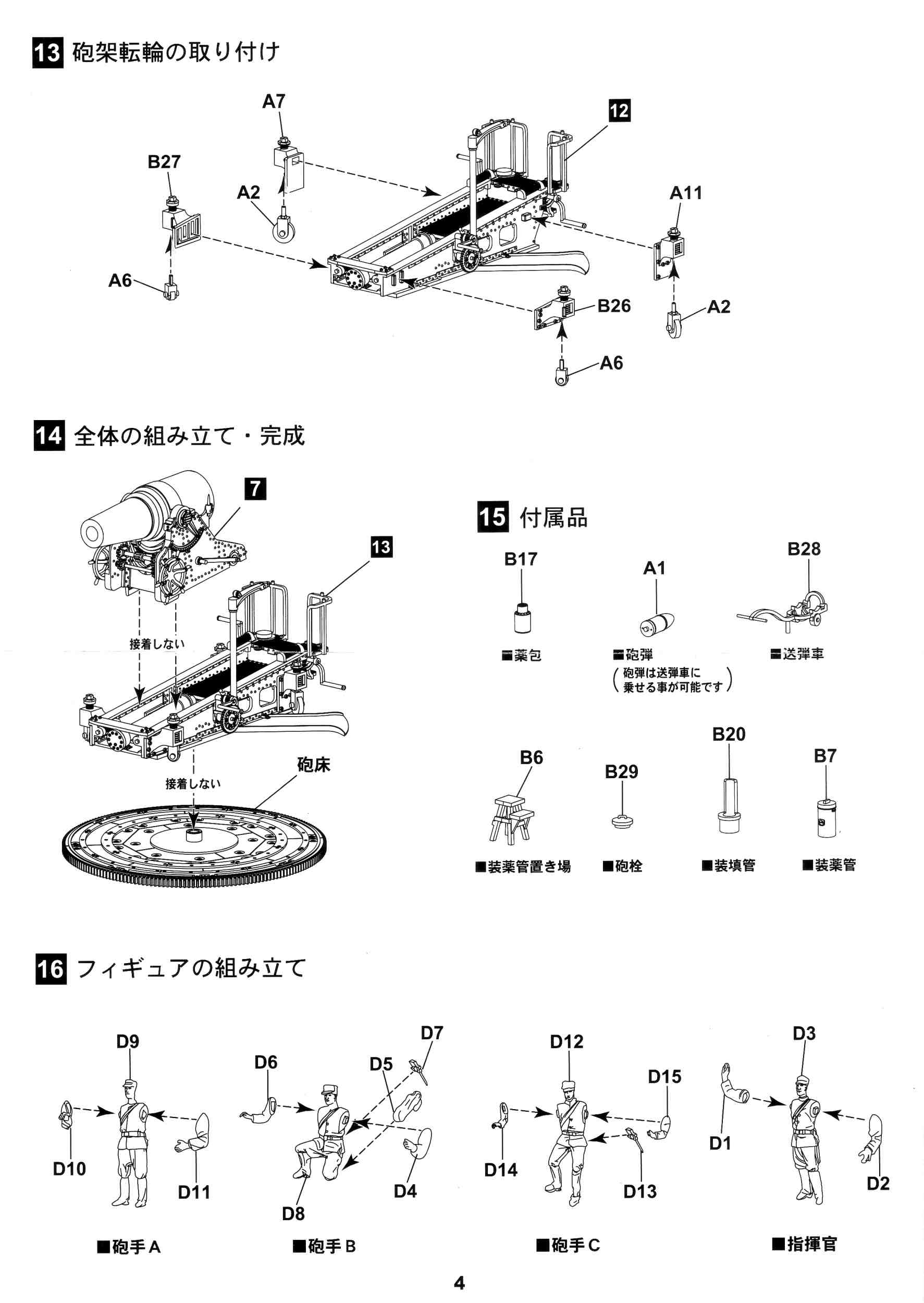
the open position and add a handle. Attaching the wheels in Step 13 so they would touch the turntable required some thought. I settled on this procedure:
The railing on the rear platform (part C19) was thinned with copious scraping using my hobby knife. I had really wanted to replace this
with bent wire but had no idea exactly how to do this, so I settled on scraping the plastic pieces instead. Many of the smaller parts were left off until the painting was finished to prevent breakage. This included part B33,
the two elevation wheels (part A4) & the crank handle (part B4) for the crane. From a couple of reference pictures it appears that the two barrel elevation wheels
(part A4) should be mounted so that they are 45os out of sync with each other, i.e. the handles should not match up side to side.
The same applies to the turntable cranks (2 x part A8) that should be 180os out of sync as
shown in the instructions at Step 10. The screw breech assembly (parts B9/B22/B25) made in Step 2 is just a smidgen smaller than the opening at the rear of the barrel so care must be
taken here to avoid having it sit crooked. The parts at Step 15 are all separate and are not referenced in the previous steps of the build. Most are obvious as to what they
are, such as the stool (part B6), the muzzle cap (B29) and shell trolley (B28), but I have no idea exactly what part B20 is. I eventually glued it to the rear platform as per a couple of my
reference photographs.
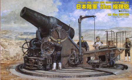
About the only really let down in the kit is with the gun crew figures. The bodies are moulded well enough, but the faces appear
to be quite indistinct. The body of the tallest figure (part D9) measures out to about 0.86in, or approximately 5ft 2in in real life. This is quite short but probably
reasonable considering the stature of the average Japanese soldier of the period. Painting Pretty much everything is painted black. However to get the look of a gun that's been fired many times with dust settling
on various surfaces, my painting went kind of like this:
Conclusion References
Review sample purchased by the author. |
| Back to Pit-Road Kit List | Back to Construction Reviews |
Article Last Updated: 20 October 2011 |
Back to Home Page |