|
In late 2019 I
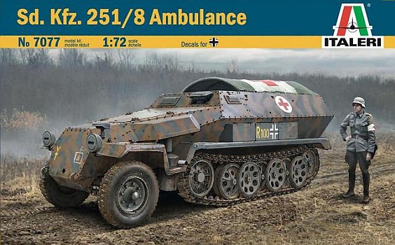
received from Italeri a preproduction sample of their Sdkfz 251/8
which was going to be released in early 2020.
The kit is the old ESCI one of which I'm familiar, having made some
of them in the '70s. The hull variant proposed by the kit is the riveted
Ausf. C. As far as I've found, this variant was built only by Boehm
Leipa, a Czech company which initially couldn't weld the steel plates
so in the meantime they produced the hulls by riveting.
The moulds I received were light grey (when I made my ESCI versions
in the '70s, they were dark grey) while the link and length tracks
mould were in a strange, semitransparent white plastic. Production
kits will have metallic grey plastic. Luckily there is no trace of
the terrible soft plastic tracks one found in the '70-'80s releases.
Production kits will also have instructions and a decal set. I've
found images of both surfing on the net. There are also two figures,
an officer and a soldier who should be placed behind the forward MG.
The halftrack is split in three sprues. On two of them there are the
basic pieces to make the generic vehicle. Despite this, the tools
are separate parts, something that's ignored on more recent kits.
The way ESCI attached the hull to the sprue poses a problem: the sprue
attachments lie on the riveting lines and this means that careful
cleaning is needed. Despite this, some riveting will be surely lost.
A solution could be converting it to a welded hull, though the conversion
shouldn't be limited to just erasing the riveting. The hulls weren't
identical and some differences can be immediately seen in the air
outlets on the bonnet, or the overlapping upper hull.
The fourth mould has two stretchers, a single seat, two straight rods
and four tarpaulin supports. There is also a barrel. On the Italeri
instruction it is omitted, while it was present in the original ESCI
one. I've seen very few 251/8 photos on which the barrel was present,
just on a halftrack captured by British soldiers in North Africa and
actually exposed at Bovington.
ESCI at its time, and now Italeri, aside from the 251/1 troop carrier,
can put on the bench some different sub variant adding a fourth specific
mould to the two generic ones:
251/1 with rockets launcher
251/7 engineer
251/8 armoured ambulance
251/10 with a 3,7cm PAK
251/16 with flame thrower
As references I used the Squadron Signal SdKfz 251 in Action: Armor
No. 21, and the Sturm & Drang no. 3: SdKfz 250 & 251.
| |
Real |
1/72 |
kit |
| Length |
5,800 |
80.6 |
81.5* |
| Width |
2,100 |
29.2 |
31.3** |
| Height |
1,750 |
24.3 |
24.8 |
| Wheels |
190x18 |
12.2x3 |
11.0x2.6 |
| Track
width |
280 |
3.9 |
4.6 |
(for * / ** see text below)
General dimensions are almost correct being about 2 mm wider. Also the
tracks are too wide, but at the end the thing is not so perceptible.
About the width, if I'm right, the overall width
is 2.1 mm wider (** I measured it out of the tiny moulding running
along the edge) and the naked hull (using a 1/35 scale drawing as
reference) is 1.0 mm wider. This means each mudguard is just 0.55
mm too wide, but not evenly. The forward part (around the wheels)
is more correct, but going backward the width grows and reaches the
maximum at the rear corners.
The model has little discrepancies on the nose area (lower hull),
the rear hull angles and on the mudguard shape. Anyway the overall
shape looks well as depicted and these are not perceptible.
A critical point of this kit would be the interior which is very poorly
rendered. About this there is something to say. The rear compartment
was often closed by a tilt laying over the arched supports. If one
wishes to make his model in this way, the first part of my review
is useless and he can jump directly to the exterior part. I have made
a choice regarding the interior. I choose to ignore a detail common
to every riveted vehicle: on the inner side of each riveted plate
there was a flat rod with each rivet other head. I'm not so finicky
at the end. I detailed the driving compartment not knowing what could
be seen after having closed the hull. Well, the answer is very little.
But I have no regrets; it's part of the modelling enjoyment, I think.
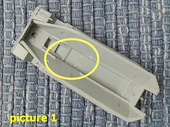
Interior
- I
had to file off a part of the ridge (see picture 1 below) present
on the lower hull inside to allow a correct placement of the floor.
- The
four mudguard interlock holes are very visible. I filled them using
plastic and cyanoacrylate glue. The two in the engine compartment
will be hidden by the firewall.
- The
floor interlock for the firewall interferes with it. It needs to
be modified for a correct fitting.
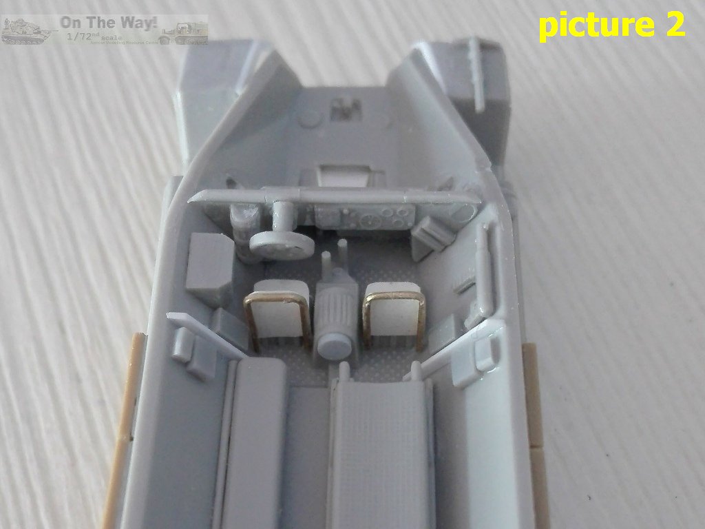
- The
steering wheel wasn't placed as normal. It was placed turned at
90°. I made a new support and glued the wheel in the correct
position.
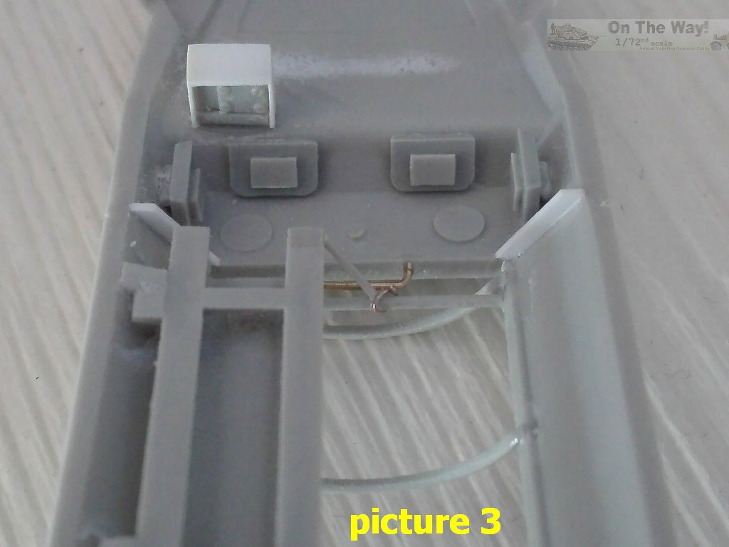
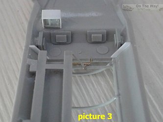
- The
bolted part of the unused piece 41A gave me the idea to use it to
make something which could imitate a radio in the shadow of the
interior (see picture 3 below).
- I
glued a circular piece to the water-barrel above the gearbox (a
251/8 feature) to give the idea of a rounded item.
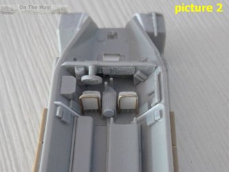
- The
seats are undersized, I replaced them with plastic and metallic
wire (see picture 2 below).
- I
added the flange just behind the driver seat which keeps the forward
half to the rearward half together.
- I
added the four interior parts of the armoured visors by plastic
pieces. They are not heavy detailed because they will be barely
visible.
- Using
plastic pieces, I made the bin, the cases for the spare armoured
glass, and the MP40 magazine housings.
- The
MP40 was glued at the radio operator station.
- I
engraved the rod of the sledges for the stretchers. The lower sits
a bit too high and doesn't allow the presence of a wounded soldier.
I filed the shims. On the wall aside the stretcher there were three
panels not visible at hull closed. I ignored them.
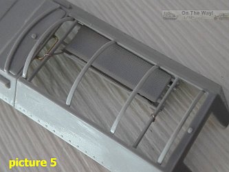
- I
didn't understand how the upper stretcher would stay in place following
the instruction. In real life it was hinged to the outer side and
two chains secured the inner side to the transversal straight rods.
To make the hinges I found the unused door hinges useful (see picture
5 below). Their dimensions are quite exact and the gluing edge was
filed to reach the hull plate inclination. To have a horizontal
position I glued the two parts on a glass. The chains were enclosed
by a flexible rubber pipe. I made them using stretched sprue; the
exposed first rings were made by thin metallic wire.
- The
foldable single seat was placed on a hinge glued to the wall. It
had a foldable support.
- The
benches were foldable and I used them without modification, adding
just the hinges. On the photo I've seen, the forward bench look
as long as the stretcher.
- Using
stretched sprue I made the locking system on the starboard door.
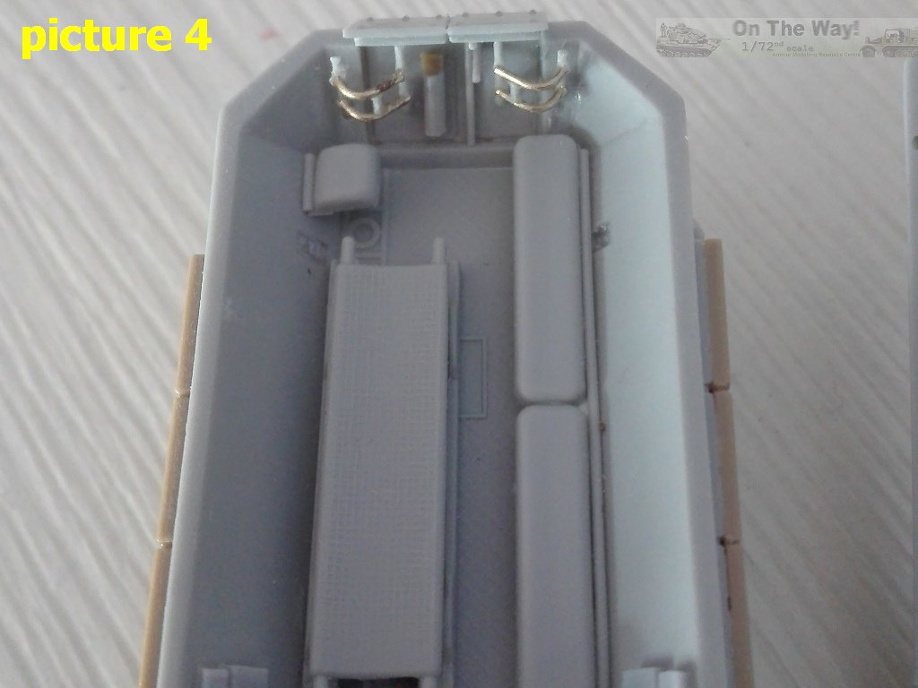
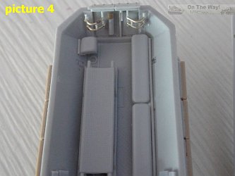
- And
the best for last. The rear door hinges were something very different
to the "L" shaped affairs given in the kit. Four vertical rods connected
by four bent rods coupled by four smaller rods. Patiently I rebuilt
the hinges withstretched sprue. They are not as detailed as the
originals, anyway now they look more realistic (see picture 4 below).
Exterior
- Some
trimming was needed for a correct alignment of the hull front where
the plastic was a bit in excess (possibly not a problem on production
kits).
- The
thickness is huge on piece 40A (radiator cover). I filed its edges
and the hull corresponding to have a 45° joint. Its hexagonal
shape is not correctly depicted being a bit narrow on the folded
edge, but to correct them requires altering the lower hull and making
a new piece with riveting. Another easy to do correction: I rounded
the transition line between the hexagon part and the lower rectangular
part by sanding. The original part was a single bent piece, not
two riveted or welded together. These correction made the length
correct for the 1/72 scale (see table above).
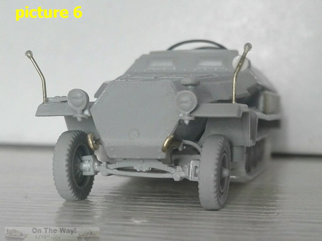
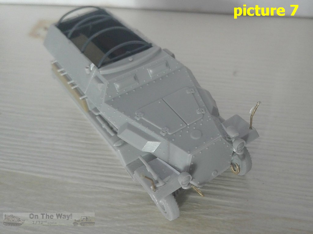
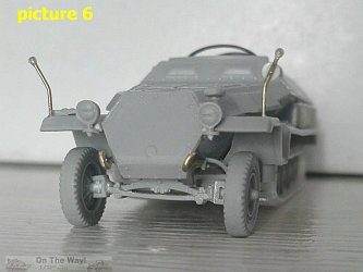
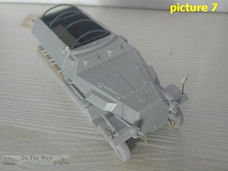
- At
the sides of the front there were two hooks. I made them with metallic
wire shaped by a file and sand paper (see pictures 6 & 7 below).
- The
lateral visors were smaller than the frontal ones. Furthermore they
were placed too far forward. I carefully removed them to be replaced
by scratch built parts by shaping a sprue segment, not a masterpiece
but no worse than the moulded ones. The double vertical rivet lines
were lost. Nothing major. These were placed at the side of the joint
line which runs below the roof edge, so their position is too much
rearward. I engraved the joint.
- The
bullet splash guard doesn't always appear on the photos I've seen.
Being unarmed, the thing looks logical, I didn't find an explanation
but what I can suppose is that some troop carriers were converted
or taken from the production line. I left it in place after having
carefully sanded two sinks in the rear part of the roof. I also
used stretched sprue segments to make the plugs for the MG unused
supports.
- I
fashioned the handle on the edge of the roof using metallic wire.
- The
lower part of nose is not correctly depicted. I didn't find a photo
or a blueprint of an Sdkfz 251 underside and the few photos I've
seen of this area showed another layout. I used a 1/35 Dragon kit
as guide because it looked to match the photo. Without going crazy,
I removed the boxes and replaced them with two pieces of plastic.
One shaped as the engine belly and the other as the sprockets transmission
cover. This didn't restore at 100% of the original, anyway
now it looks better than before (in my opinion).
- The
front axle suspension is too much spaced and the wheel muzzles are
placed on the lower edge instead in the middle. I cut the piece
in four parts and reshaped the suspension. It is also placed 1 mm
forward. I filed the interlock and repositioned it.
- The
wheels are just a bit undersized. If one has a couple of spare tires
they could be replaced. The rim has two concentric edges. The outer
is 7.5 mm and the inner is 6.5 mm, which is more correct for an
18" rim.
- I
added, using stretched sprue, the steering rods, one between the
wheels and another along the hull side.
- The
"V" shaped stabilizer for the transversal suspension system is not
well depicted. I made it by stretched sprue.
- The
track wheels had a torsion bar suspension system. I added the arms
from plastic strips.
- The
central track wheel row should be composed of two separated wheels.
If one wished they could engrave the rubber thickness. I didn't
in a moment of laziness. The outer wheels have the holes a bit smaller
and too near to the hub. There is nothing to do about but replace.
I kept them.
- I
added the hub covers which are absent in the sprockets, the wheels
and the idlers, using plastic rods.
- The
tracks miss the central guide teeth and are 0.7 mm wider. I left
them as they are.
- The
mudguard front flaps are too long; I filed them to the correct length.
The first time I measured them in the nose area and then I realized
too late that they are not parallel. As already mentioned earlier,
their overall width grows. Too late. If I had realized this earlier
I could have filed off 0.5 mm on the rear inner side. To keep them
parallel I modified them with a 0,5 mm shim near the engine area.
- During
the cleaning of the mudguards part of the edge was lost. I replaced
it by thin stretched sprue.
- On
the forward corners, I made the width indicators using metallic
wire and a drop of glue.
- The
bins on the mudguards are pushed too much inside: their doors opened
downward hanging vertically. I realized the problem after having
glued them, so I replaced the doors with plastic. I could also shim
the inner side. I also replaced the locks which were placed over
the bins.
- As
for the shovels, they look better if the blades are bent downward,
being aligned to the handles.
- For
a proper placing, the track sub-assemblies were glued after having
placed the mudguards. If glued first, the front of the track could
touch the mudguards. This meant I had to reshape in place the rear
edge of the pieces 58A and 59A.
- When
the tracks were placed, the rear of the hull gave me a strange look.
After a little research I found the reason. The plate under the
hook is too high, because the belly wasn't straight. From the last
track wheel to the idler it was sloped. I reshaped them and the
look is greatly improved (in my opinion).
- I
shortened the towing hook overhang, looking too prominent. After
having glued in place, I cut it off. After having drilled the square
base I glued the shortened hook which was also slightly enlarged
by stretched sprue.
- I
added, using plastic strip and stretched sprue, an antenna base.
- The
arched supports for the rear compartment cover can be omitted or
used covered by a scratch built cover. I chose to use them, but
as their thickness is excessive, I thinned them before gluing in
place.
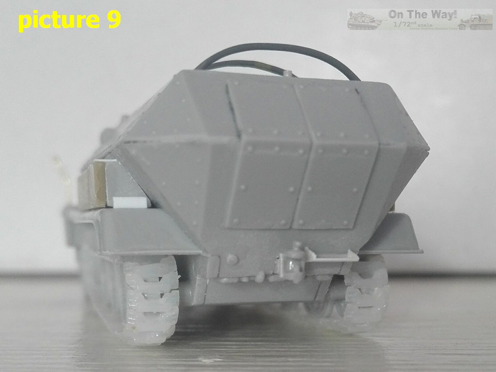
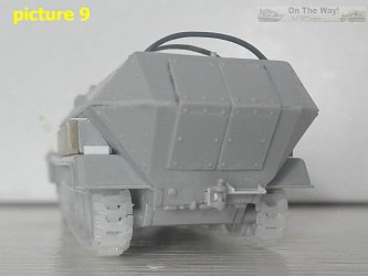
- A
251/8 feature missing in the kit is the step under the starboard
door. I made it by plastic sheet and stretched sprue (see picture
9 below) .
Decals
The sample I received didn't come with decals. Production kits have
a well detailed set for three armoured ambulances. I couldn't be sure
about their correctness because I didn't find the photos of the original
vehicles, but I found photos of vehicles which could be.
- WH1262755,
R100, a Stab. Pz.Div. 16 in Russia, 1942. I don't know if this is
referred to the same photos I have. If so in my sources the divisional
markings are not visible and it was an Ausf. B.
- WH1264768,
Stab. Pz.Div. 21 in North Africa, 1942. Quite generic, I didn't
find its specific photo.
- no
plate number, unknown unit, Russia, 1942. As for R100, I found a
photo of a 251/8 which looks like the depicted vehicle (it's hard
to say without the plate numbers) but this too is an ausf. B.
Conclusion
At the time ESCI released their Sdkfz 251s they were the only in 1/72
plastic kit and they looked good (old rubber tracks apart). Currently,
more precise and detailed (though not perfect) moulds by Dragon and
Revell make this a simplified kit in comparison, placing it at an intermediate
level. Despite this, if one is not scared by the old school way, with
some white plastic added here and there, and the needed care, it can
still be made into a quite good display model, if one can live with
the wider dimensions (that if one works on the mudguards is limited
to 1 mm). About the interior, my job at the end resulted in an almost
futile exercise because very little resulted visible after having closed
the hull.
On the other hand, while Dragon and Revell have every other variant
of the introduction list, currently this is the only /8 and its specific
parts could be used with another kit to make an ausf. C welded hull
or an ausf. A, B or D, making this kit useful in another way.
Review sample supplied by Italeri.
Italeri
products are available at

|