| Clarktor-6
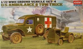
The tractor of the Academy ground vehicle set #4,
is the Clarktor-6. Already reviewed
by Al Magnus, it is a very small project. Just 25 pieces compose
the model. Despite this I found it not so easy to do. The pieces are
made from pine green plastic and fit quite well. The only decal supplied
is a star for the bonnet top. No registration number or bumper codes
are present in the set. This is not a real problem because as far
as I've seen most were quite anonymous.
Understanding the right variant depicted by the kit gave me some problems
because little info is available. As far as I've found, Clark produced
no less than 17 sub-variants from 1940 until the end of production
in 1963. A main feature divided the production; the "light duty"
type had single rear wheels while the "heavy duty" type
had dual rear wheels. The larger mudguards thickness served as a counterweight.
The Academy kit is obviously a "light duty" type, but the
fuel filler cap at the right of the seat tells us it depicts a CT21
or CT30, two post WW2 variants built by 1950. Good for Korea, Vietnam
and civil aviation (where this tractor saw use up till the 80'es),
the Academy variant is too late for my interest.
The 1945 Technical Manual TM 10-1619, from page 126 to page 170 (Chapter
4 -Tractor warehouse) lists 4 variants in service in the US Army:
the Standard 24 and the Mill 33 with single rear wheels, the Mill
44 and the Mill 50 with dual rear wheels. Based on the kit model dimensions,
to make a WW2 variant, I could only make the Mill 33 because the Standard
24 was 5 1/4" shorter. Making a "heavy duty" Mill 44
or Mill 50, is possible anyway with a little more plastic sheet and
another rear wheel couple.
I didn't find the registration number batches list, which first digit
was 8 for wheeled tractor.
Examples (heavy duties are in italic) taken from WW2 period photos
are 8650, W8735, 81425, W86046, W86807, W87899. Strangely enough,
on two Clarktors the registration number didn't start with 8: W3015,
56930.
As far as I've found, also the Royal Air Force received at least 1,512
Clarktors.
Dimensions are quite correct.
1/72 kit
About the wheels, I didn't find the correspondence in the tire chart.
The diameter I have calculated should be (diameter x tire section)
about 7.6 x 2.2 and 11.2 x 2.7.
Having altered the steering column I don't know how high the model
would be OOB, however I could adapt mine to the correct height.
During its longtime military and civil career, the Clark tractor saw
local modifications, so different features can be seen in photos regarding
the shield, the bonnet, the steps, the seat, the wheels and the pintles.
In this perspective, tires apart, the Academy kit can't be seen as
a totally wrong kit and it could depict a single specific tractor.
But I'm not a post WW2 civil vehicle modeler...
Helped by the limited info and photos I found, here is what I made
to improve my WW2 airfield tractor.
| |
|
1/72
(mm) |
kit
(mm) |
Length*
|
99
1/4" |
35.0 |
35.8 |
Width
|
52" |
18.3 |
18.6 |
| Height
** |
58
1/2" |
20.6
|
see
text |
Wheelbase
|
58
7/8"
|
20.8 |
21.4 |
Wheel
(front)
|
6.00x9
|
see
text |
no |
| Wheel
(rear) |
7.50x16
|
see
text |
10.0x2.5 |
*
without the pintle.
** to the top of the steering wheel.
Chassis
-
One of the major faults of the kit is about the wheels. I turned
them inside out because their outer side is shallow and then I reworked
them to make the rim closer to the originals. They are still not
perfect, but they looked greatly improved to me. I filed off the
hub from the rear ones and gave them the raised part of the rims
from punched 0.5 mm plastic sheet. Then I made the spokes from 0.5x0.5
mm plastic rod. Rounded plastic rod slices were used to make the
hub and the bolt heads. The front ones had the tires filed to have
smooth sides and the hub sanded down as much as possible. A new
hub was created from rounded plastic rod slices.
-
The ejector pin marks present on the underside were filled.
-
The four leaf springs are made as solid "D" shaped items
instead of metal bows. Their top was filed to give them a more likely
look.
-
I added the steering gear from stretched sprue.
-
The missing exhaust piping was added on the opposite side following
the layout suggested by Al Magnus’ civil postwar model. In
the better tradition, I find a photo of the original WW2 layout
just after having painted the model. I corrected my model; the new
muffler was placed just behind the rear bumper in the place of the
huge member. I couldn’t remove the second muffler, which became
a rounded shield added locally.
Body
-
Absent in the few period photos I've seen, the piece O16 went in
the spare box. Their interlocks on the right fender were closed.
-
The ejector pin marks I could reach were filled.
-
I closed the empty space under the seat with thin plastic sheet.
Here was the fuel tank in the post war variant.
-
The shield O28 is not correctly depicted. I removed the strip because
it is missing in every WW2 period photo I've seen. For the same
reason I closed also the bottom edge notch. As correctly pointed
by Al Magnus, the number of holes is wrong. A column is missing
on both sides as well as three rows too. Unfortunately the shape
and the hole dimensions don't allow adding the missing holes. Anyway,
there is space for four holes below the bottom row. I drilled them
as well as the two holes for the removable hooks. This gave it a
more likely look. The thickness was thinned along the edge. This
job didn't give me a perfect piece and a photoetched part would
be a better option, but the only one I've seen (in the Eduard set
# 22111) is not correct either.
-
The two thick supports behind the shield moulded on the fender top
were replaced with thin plastic sheet.
-
The bonnet top has an engraved edge which I didn't understand and
misses the sides. I filled the gap and made the lateral panels from
plastic sheet. I opened the squared windows just to close them by
a metal PE mesh (a bit wide anyway). The lights (O6) interlock was
filled.
-
Also the radiator mesh O9 was replaced by the metal one.
-
The lights O6 were placed on the rounded edge in the WW2 period
photos I've seen. I cut them off and placed them in the correct
position after having filled the interlock.
-
There were two caps on the bonnet top. The first was the radiator
one, which was sanded down when I filled the lights interlock. The
second one is the WW2 production fuel filler cap. I made both from
stretched sprue slices.
-
The steering column base insertion was quite different. I replaced
it with stretched sprue and placed it correctly. The column was
kept in place by a "V" structure which I made from plastic
rod and thin metal strip.
- On
the right side the air filter was simulated with plastic rod.
-
I also added the driver pedals and the hand brake.
-
I removed the post WW2 fuel filler at the right of the seat.
-
I reworked the inner edge of the rear fenders with two 0.5x0.5 mm
plastic rod segments.
-
The rear bumper O7 is wrongly shaped. I replaced it with plastic
rods. The towing hook was replaced by the unused piece O4 adapted
for the new placement. The new bumper also corrected the length.
Bomb lift M1
The
same tractor mould also has the five pieces which compose the Weaver
Mfg Co. Bomb lift M1, catalogue number G189. It was a 3 wheeled cart,
which was towed and steered by a T-handle by the ground crew just
like a pallet jack. It had a hydraulic platform raised and lowered
by two foot pedals (the long one raised it, the short one lowered
it). It could lift bombs up to 900 kg (2,000 lb) under the aircraft
fuselage and wings.
The Academy body is solid and the T-handle has a solid ring that left
me thinking it could be towed by the tractor. The platform shape is
wrong. The lifting gear details are shallow. The pedals are missing
and the T-handle is incorrect.
This
time I found no more info and also the restorer community doesn't
look very interested in this item. I didn't find its real dimension,
so I cannot give assurances that the scale is correct.
Using just photos, I tried to improve the cart.
-
The first thing I did was to hollow the body, then I made the new
platform and the "L" shaped front member. In the mid of
the platform there were three holes. I drilled them open (a bit
larger I think).
-
I made the lifting gear from plastic rod, stretched sprue and a
thin metal wire wrapped around a stretched sprue segment to make
the coil spring.
-
On the front I added the pedals from 0.5x0.5 mm rod and thin plastic
sheet.
-
On the rear axle I added the trapezoidal sheet and the towing point.
-
The T-handle was replaced with stretched sprue. I left it lying
on the ground slightly turned. An optional position can be achieved
turning it 180° and leave the T-handle laying on the platform.
The thick washer O5 went in the spare box. The new steering insertion
point was made from plastic sheet to which I added the bolt heads
made from stretched sprue slices.
_t.jpg) _t.jpg) _t.jpg)
 _t.jpg) _t.jpg)
 _t.jpg) _t.jpg)
Conclusion
Looking at the improvements that are required, it can't be seen as
a kit for beginners. It is a pity, because both are very nice pieces
to add on the concrete runway of an airport. They need important surgery
if one is finicky like me. The wheels need to be replaced (as already
pointed out by Al Magnus; the front ones are simply horrible). A correct
PE piece for the shield and another for the platform would be a great
help. A great feature of this kit is the wide period during which
both pieces can be used, from WW2 until the modern jet era.
This
model can be purchased from

|

.jpg)
.jpg)
.jpg)
.jpg)
.jpg)
.jpg)
.jpg)
.jpg)
.jpg)