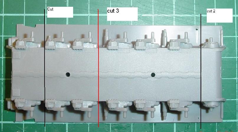
It has often been said on various modelling forums that the tracks on the Dragon Challenger 2 are too short !! I beg to differ!! The tracks are exactly the right size, it is the hull that is too long and thus the wheel spacing is too wide. In this article I will set about showing where the hull is a fault and how to go about correcting it, The process is fairly simple in execution and should be within the capabilities of all but the very novice model maker. The hull in the kit comes in 4 parts, upper, lower, rear plate and the front plate. The faults lie mainly with the upper and lower hull parts. The lower hull The lower hull comes moulded as a single piece with the hydro pneumatic suspension housing in place. The lower hull is wrong in three places, although you will only need to correct two of them as one is so small, that I found it just not worth the effort of correcting it, I will show it for those that are curious about where it is.
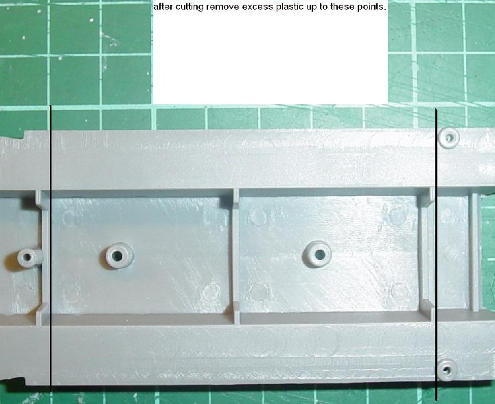
Cut 3 is the one I found to be not worth it as the distance is only about 0.3mm. The other two cuts will leave the hull in three parts. The front part needs the plastic removing up to the strengthening bulk head on the inside, as does the Middle section, shown in the picture below.
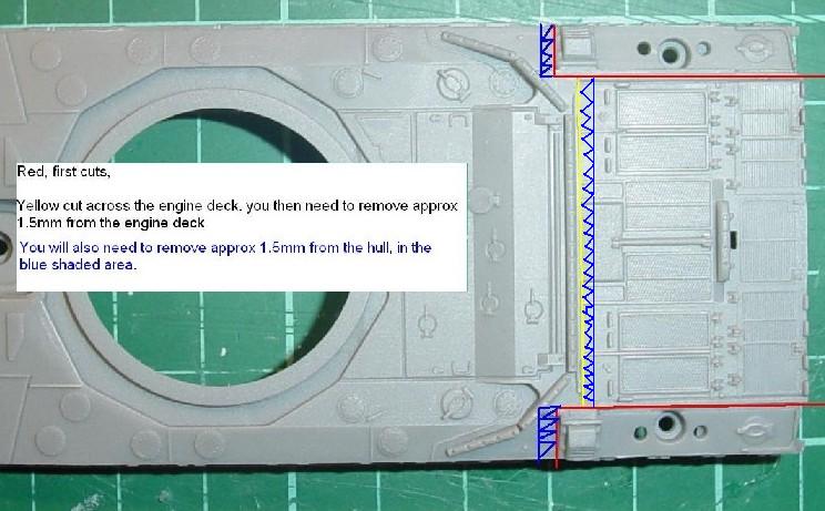
Because the picture was taken with a digital camera, it has some come out a bit rounded !!. Remove the plastic to the bulk head making sure that everything is straight. The upper hull The upper hull is a bit more involved but is never the less, pretty straight forward. The problem with the upper hull centres around the engine deck but thankfully it is only in one area. The best reference for this, is the Revell Challenger 1 kit, The Challenger 1 and 2 share basically the same hull, with a lot of minor changes between the two, but the size of the hull and engine deck are the same.
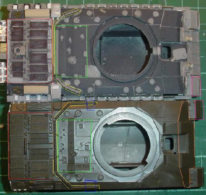
The red lines should be the first cut that you make, they are down each side of the engine deck, then in at right angles along the edge of the exhaust outlets. With these pieces removed, the next cut (yellow) should be straight across the engine deck, just behind the gun bump stop at the end of the Reccesses where the engine deck grab handles are. Once you have removed all the pieces, you then need to remove about 1.5mm from the engine deck and also the same amount from the hull, shown as the blue shaded area's on the picture. Now comes the hardest part, fitting it all back together so that it is all straight and all lines up corretly. You will need to replace the material removed when sawing down the sides of the engine decks (Red lines) with thin plastic card or strip. The easiest way that I found, was to assemble the front two pieces of the lower hull together, and then fit these into the front section of the upper hull. I then assembled the rear, comprising of the rear lower piece, the rear plate, the engine deck and the two outer pieces as a seperate piece, once dry I then fitted the two assemblies together making any corrections neccessary to ensure that all was straight. When finished the hull will look like in the picture below, shown along side the Revell hull for a size comparison, it also shows some of the major differences between the two hulls and why the Revell hull can't be used for the Challenger two hull.
PART 2 Will be about the turret and the corrections to the rear of the turret.
PART 3 Will be about correcting the add on armour to fit the new sized hull, along other details that can be done (depending to which level you want to model. |