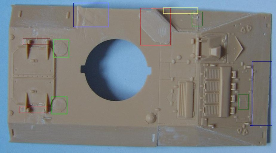
Hull corrections With the lower hull almost complete, we turn out attention to the upper hull, here is where many of the faults lie and so most of the work centres around the upper hull. A lot of it is cosmetic, but there are also some major points that should be done to produce a better Warrior. As I have said before, it is up to you to decide how much of this you want to attempt, as only you will know your own "skill" level, I don't particularly consider myself to be a skilled modeller, but what I am is dogged, and will use prehaps unconventional methods to achieve my goals. I am a great believer in trying and although it takes a few tries to get it right (as my dustbin will testify) just by attempting it you can possibly find a way that is easier for you, rather than sticking rigidly to the way described to you by someone else. The best way to start, is by removing all the offending items before rebuilding anything, this includes the engine access hinges, moulded handles, the periscopes above the troop compartment (but not the circular mounting plates they are on), the troop compartment roof hatch hinges, the air intake to the to the left of the turret and the breather to the rear, the tool mounting bracket in front of the louvers. With these items removed you can now start to rebuild the hull.
In the picture above, the more observant of you will note that I have also removed the exhaust from the RHS, this was due to there being a detail error on how the side plates meet the glacis plate, this is apparent on both sides of the vehicle, but it is difficult to correct and not included in this article. The exhausts will be replaced by using the exhausts from a spare hull top, obtained as a left over from the CMSC MRRV conversion. The first thing that needs to be done, is the access panel to the left of the driver, the kit shows this hatch extending down to the lower edge, whereas it needs to be raised so that it ends 2 mm before the edge. This is a fairly simple operation, done by shaving of the old detail and replacing it with plastic strip further up. The hinges for this panel also need to replaced making them 90 degrees to the plate rather than vertical, when replacing the hinges, they also need to be moved up slightly. Moving down the LHS we come to the air intake, this needs to be made higher and it was easier (for me) to remove and fabricate a new part than try to modify the kit. Interestingly the plate behind the intake which is actually a plate to close off the intake, is the correct size and shows the correct height for the intake.
The same can be said for the roof vent behind the intake, although here it is the bevelled edge that is missing rather than any dimesional error. Moving around to behind the turret we come to the troop roof hatches, here the hinges need to be replaced with plastic rod. Forward of the hatches there are the two roof mounted periscopes, these have a distinct shape, not captured in the kit, these must be rebuilt from scratch, unless you have access to the old 1/87 CMSC Warrior kit in Resin and White metal, which I believe is still marketed under United Fun on their web site, this kit had the periscopes as seperate items, and although they were supposedly 1/87th scale they work well for the Revell Warrior (also for the laoders periscope on the Challenger). The 6 bolts on the circular mounting plates will have to be replaced before attaching the new periscpes. Moving forward from the periscopes we come to the fuel filler cap, this has the wrong profile in the kit and needs to be flattened slightly, doing so will mean losing the latch detail, so this must be replaced. Moving further forward are the engine louvers, on the real vehicle these are covered by a mesh, which is not provided in any of the aftermarket PE sets. Also the armoured cowl is moulded in situ, making modification tricky. However there is one good point, because the armoured cowl itself needs to be changed, makes the changes easier. The armoured cowl, as it is moulded is too short and too shallow, and needs to be built up in height using Miliput or other putty, the length can be made up by adding plastic strip to the rear, this also has the effect or creating an undercut at the rear. In front of the louvers are the Horizontal engine access plate hinges which need to be rplaced with hinges the are 90 degrees to the plate instead of the kit ones which are verticle. In front of this come the tool mounting bracket. Moving down the RHS, a demarcation line neeeds to be added between the 2 exhausts, 6 bolts need to be added to the front triangular portion. A point to note, is that if the drivers hatch is to be replaced, by either the CMSC part or a scratch built part, it is an idea to remove the hatch inside of the actual hatch, the remaing can then be thinned from the outside to produce a lip for the hatch to sit on. The picture on the left shows the hatch after modification.
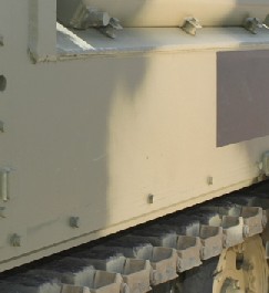
further down we encounter the stowage basket, the moulded mesh is alignd vertically whereas it shoud be aligned diagonally, you can eithe elect to replace the mesh, or go the whole hog and replace the whole basket, in doing so, you can also correct some detail. The lowere edge of the basket, instead of being vertical as in the kit should be at 90 degrees to the plate on which it is mounted, the basket can then be built up using plasticard for the sides and strip ofr the front, the mesh can be place behind the strip, You can also use the PE set from Extratech, but this is also missing the detail at the bottom. The next thing to do is replace all the grab handles around the engine with ones made from thin wire, this also includes the ones near the exhaust. The main upper hull and side can be assembled together, including the rear door plate. Before attaching the rear stowage bins to the rear plate, they will need to be modified, the kit bins are too short and need to be lengthened, you can either add the extra length to the back or to the front before adding the door, if you add it to the back (as I did) you will need to remove the moulded on X on the sides and the 3 bars on top, however the fastening latches can be retained. Doing it this way you will have to modify the light clusters as they will now extend too far to the rear. If you add the plastic to the front of the bin, you will have to remove all moulded on detail including the fastening latches which will then have to be replaced. Moving to the rear door, the door mounted fire extinguisher os mounted to low on the door, the lower attachment hole needs to be filled, and the upper locating lug from the bracket removed, this now makes the upper whole the location for the lower lug on the bracket. After attaching the upper hull to the lower, one other thing needs to be done, but only if modelling the vehicle without, side skirts, (as with it wont be seen), is that a small strip of plastic needs to be run either side under the sponsons, it can be either full depth or just a strip. The strip needs to be set back from the edge to make a visible step at the bottom.
|
 The plate for closing the intake
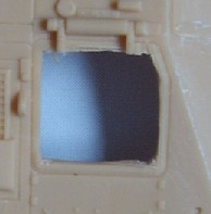 Drivers hatch
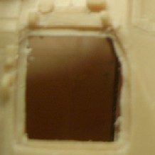
 Step in lower hull