| Preliminary
remarks:
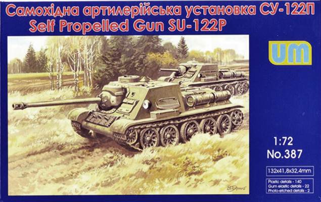
For a preview of this kit, see here.
I wanted to build a "what-if" vehicle, assuming the vehicle
went into production at the end of the war and was captured (and used)
by the Germans.
Some
history
SU-85
July
1943 - August 1944. 2339 vehicles.
Rear
plate of superstructure is sloped.
Bulge
to the left of the gun in the glacis for the gun sight.
Early
vehicles (1943) had appliqué armor for the commander's cupola,
rounded beak, 4 bolts for the gun collar instead of 6 and no track
links on the bow.
Early Summer 1944: smoke dischargers installed on rear plate.
SU-85M
September
1944 - November 1944. 315 vehicles.
Basically
the same as the SU-100, but quite a number of changes with respect
to the SU-85:
- vertical
rear plate
- no
bulge for gun sight in glacis
- pistol
port in glacis moved inwards
- pistol
port on left hull side dropped
- round
commander's cupola that extended beyond side plate
- different
gun mount
Late
vehicles had the same, wider, gun mount as the SU-100 (but with a
different collar).
SU-100
November
1944 - well after WW2. +/- 1400 produced during the war.
Slightly
different gun collar with respect to SU-85M.
Before January 1945 twin hatches for the commander were used, afterwards
a single hatch.
Late vehicles had a loader's hatch that extended into the rear plate
of the fighting compartment; early versions only had a pistol port
and vision slit.
Late vehicles (post-war ?) no longer had the plate to eliminate a
shot trap between the fighting compartment and the engine deck.
Kit
features:
- Superstructure
of SU-85M/SU-100
- Gun collar
of SU-100
- Single
hatch for commander
- Loader's
hatch doesn't extend to vertical rear plate
- No
plate for shot trap (as does none of the UM kits)
- Starfish wheels
Apart from the
wheels, the gun collar and plate for the shot trap, this is mostly
correct, based on the pictures of the prototype and the features typical
at the time the prototype was built.
Construction
Step
1-4: assembly of lower hull.
While
the boxtop shows the early blunt nose, the kit instructions want you
to install the sharp nose. I went with that, as the prototype already
had this nose [1].
Note that the rubber tyres (part 2F) are not symmetrical even if they
would appear so at first sight. If you don't pay attention, they will
not fit properly.
There are no alignment pegs for the wheel halves. Pay attention that
the holes lign up.
Note that the prototypes of the SU-122P, apparently like all SU based
on the T-34, had solid wheels. I do not know why UM chose to give
spider wheels, but it went well with my "what-if" concept.
Admittedly, they were sometimes fitted in the field as replacements,
as were all-steel wheels.
In my kit, some of the wheel halves had flash, while others had incompletely
formed hubs. I decided to replace the front wheels with steel Panther
wheels. (Quite a number of T-34s and derivatives thereof were fitted
with Panther wheels as an expedient repair, even though I have no
documentation of the use of steel wheels.)
If I am not mistaken, then the swing arms labeled "33A"
should go on the right while "31A" should go on the left.
I have the impression the instructions are wrong here. The separate
swing arms are a very nice touch if you want to articulate the suspension.
At this point I would recommend not gluing the drive wheels (which
are at the rear on the T-34) to ease the placement of the tracks.
I kept the latter off until the upper and lower hull were mated together.
Step
5-8: upper hull
I gave
it some thought, but couldn't find any reason why mating the front
and the rear of the upper hull first, before gluing them to the lower
hull, would be a good idea, so I decided to add the front of the upper
hull to the lower hull first after which I added the engine deck.
Worked fine.
Parts 114D and 176E (gun mount) fitted badly. I think I added them
to the fighting compartment too soon; I should have worked more on
the gun assembly before doing that as it gave me all kinds of trouble
the way I did it.
Very late in the painting sequence, I lost part 80B (antenna mount).
There was no other solution then to scratchbuild a replacement.
I decided to fit fewer handrails and replace them with metal wire,
as removing and sanding the plastic handrails proved neigh impossible.
Their placement is solely based on my personal taste.
I also decided to drill out the exhausts. The exhaust assemblies were
added to the rear of hull on sight, as any form of locating peg is
missing. (Actually, there are no locating pegs whatsoever in this
kit, not for the exhausts, not for the handrails, fuel tanks, cupola,
or whatever.) The rear of the hull is striated, by the way, as if
it were 3D printed.
When adding the external fuel tanks, take care to assemble them so
that the fuel cap faces upwards. Did I mention that UM doesn't provide
locating pins ? As a consequence, it might be that I placed mine too
far aft (even though their position seems to vary). For the same reason
I might also have positioned the tow shackles too low.
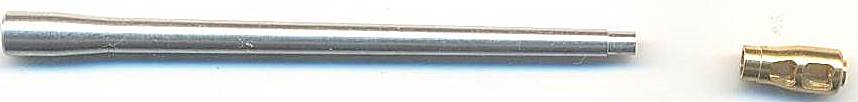
The gun barrel was replaced with a metal
barrel from RB Models, while the PE engine mesh went on better
than expected, after annealing and carefully bending it.
While the instructions make a vague mention of the tow cables, it
is not clear where they are supposed to go and they are (in my opinion)
horrible anyway, so I left them off.
As I was going to fit Schürzen, the beads on the fenders were
shaved off; I also replaced the curved front fenders with angular
ones (which are also provided) as these went better with my late war
setting.
I took some liberty with the stowage on the fenders, adding spare
tracks and sundry bits from the spares box.
Note that UM is one of the few (only ?) manufacturer to provide positionable
driver's visors. The driver's hatch can also be opened and has some
detail on the inside. As the hatch is rather big, and as the interior
is just a gaping hole, some scratchbuilding might be needed to attract
the attention of the unwary admirer.
Note
that the SU-122, SU-85, SU-85M, SU-100 had a small idler adjustment
hatch on the lower bow (on the left when seen from the front), which
is not present on the T-34. Neither is it on this kit.
A small
detail that is often overlooked in T-34 based SUs is the small triangular
plate in the area where the fighting compartment meets the engine
deck. Based on the history given above, all wartime SUs should have
had it. In hindsight, I should have added it.
Finishing
I finished
my vehicle as a Beutepanzer, which gave me a lot of freedom. It also
allowed me to avoid using the decals which looked excruciatingly flat
to me. Having heard of their appetite for silvering, I think I made
a good choice. Decals came from the spares box, with the large crosses
from a Superscale sheet for Luftwaffe bombers. These react delightfully
to setting solutions and were thus perfectly fitted to be used on
the engine deck.
_t.jpg)
Picture
from [1]
_t.jpg)
Picture
from [1]
_t.jpg)
Picture
from [1]
_t.JPG)
_t.JPG)
_t.JPG)
 _t.JPG)
_t.JPG)
 _t.JPG)
_t.JPG)
 _t.JPG)
 _t.JPG)
 _t.JPG)
 _t.JPG)
_t.JPG)
References
[1] http://www.materielsterrestres39-45.fr/fr/index.php/chasseurs-de-chars/176-chasseurs-de-chars-urss/757-su-122-p-1
[2] SU-85
and SU-100 on the battlefield, Neil Stokes, World War Two Photobook
Series 9. Peko Publishing.
Preview
sample purchased by the author.
This
model can be purchased from

|

.jpg)
.jpg)
.jpg)
.JPG)
.JPG)
.JPG)
.JPG)
.JPG)
.JPG)
.JPG)
.JPG)
.JPG)
.JPG)
.JPG)
.JPG)
.JPG)
.JPG)
.JPG)
.JPG)
.JPG)
.JPG)