|
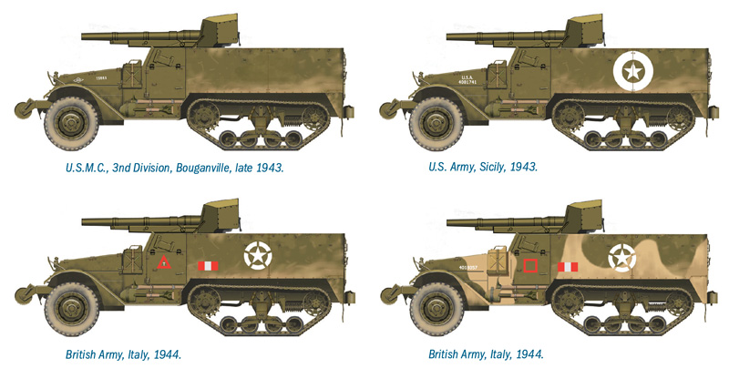
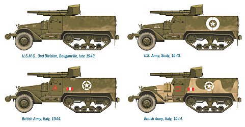
One of the variants of the US halftrack to see service in the WW2 was the M3 75mm GMC. This self propelled gun was made as an
interim tank destroyer awaiting the M10,
and equipped the TD battalions in the early stage of the war. It was used in North Africa, Italy and in Europe as well as in PTO and in CBI, by US Army/USMC and
British Army.
I was interested in making one of them because some were found in two British Armoured Car Regiments in North Europe in place of the AEC Armoured Cars Mk III
(see warwheels.net).
As far as I know, currently the only 1/72 plastic kit is the Italeri one, in their "fast assembly" war gaming line. The box contains a pair of olive green sprues,
the instructions and a decal set (photos of the kit's contents can be found in Christopher Benjamin's preview).
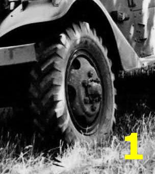
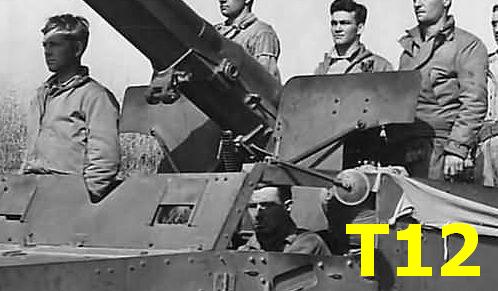
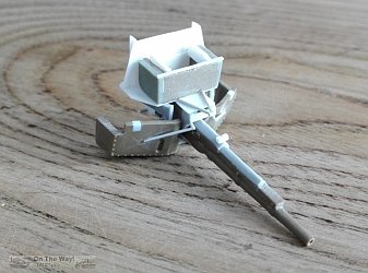
The kit is of a late production GMC. The first batch, designated T12, was produced in August-September 1941 (86 vehicles; serials
should run from 409528 to 409613, being 409545 and 409560 for sure), had a smaller gun shield (see T12 photo below), no bonnet jerrycans and wheels with six holes
(see photo #1 below).
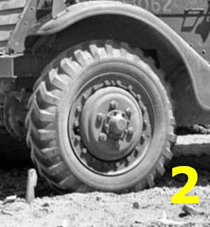
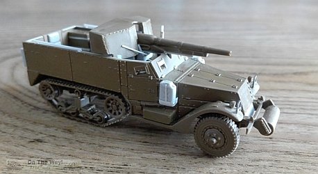
The three production batches of M3 GMC (2116 vehicles; 4017060 - 4018409, 4053350 - 4053379 and 4053724 - 4054349) had the enlarged shield that
matches the kit's part and wheels that match the kit's wheels (see photo #2 below), although in some photos early wheels can be seen.
The last production batch used the the gun that was mounted on the
M2A2 carriage instead of the M2A3 carriage, and was called M3A1
(a walkaround of the M2A3 gun can be found at
toadmanstankpictures.com). The differences between the carriages in 1/72 are
very little and are clearly explained here.
The whole production (T12 and M3 GMC) was made by Autocar and ended in April 1943.
Although I've seen a couple of photos of Canadians of what look to be 75mm GMC based on the M5 half tracks and one on the M14 half track, I didn't find info about them.
When the M3 GMC was considered obsolete, 1360 were converted to the APC role, Canadian 4053743 in Korea was an example being one of these.
About the plastic moulds, some flashes need to be cleaned here and there and shallow sink marks need to be filled. The decal set is generic and doesn't give us
specific unit badges. Although still quite thick, they are not gloss, a welcome improvement. The poor number of the pieces (15 each), the moulded on details
(like the jerrycans) and the single solid components (like the tracks set or the gun) witness this kit is not for display use. However being generally correct,
this simplified kit looked useful to me to be a good base for an improvement job.
Dimensions need a bit discussing because I find some differences between different sources I used. While width (6' 5¼"
otherwise written as 77¼") didn't
change, the length difference of an M3 APC with roller (the rear bins are missing in the kit and I needed the length without them) run
from 20' 2⅝"
(1/72 = 85.4 mm) to 245½" (1/72 = 86.6 mm). The height is almost always indicated to be 89" (otherwise written as 7' 5") and this gave me a bad
headache.
In 1/72 it means 31.4 mm, which frankly are too much. After having tried to understand something about this exaggerated dimension, finally I found a drawing
where the 89 inches is measured to the top of the canvas cover, not to the upper edge of the body. Not able to find the needed dimension, I scaled down the drawings
I have (which is not the best way to get a real dimension, I know, but there is not a preserved M3 halftrack near my home town) thinking in feet/inches
prospective and not in metric. I obtained heights about 76" (that can be written as 6' 4"). If these speculations approximate the real vehicle, the 1/72 scale hull
height should have a measure about 26.8 mm. The kit hull is 25.8 mm and for me was close enough. Having modified the gun mount, I'm not able to say exactly how
tall it is if assembled out of the box (I used the second kit for another project). My assembled model resulted 33.5 mm high, just 1 millimeter over the
32.5 mm of the scheme. The dimensions reported in the scheme came from the February 1944 technical manual TM 9-710, which I think should be an authoritative
source.
| | Real (inches) | Real (mm) | 1/72 (mm) | Kit (mm) |
Length
(M3 APC w/ roller) | 242 ⅝ | 6162.7 | 85.6 | 85.7 |
Length
(GMC w/ bins) | 249 ⅞ | 6346.8 | 88.2 | See text above |
Width | 77 ⅞ | 1978 | 27.5 | 27.5 |
Height
hull top | See text | 25.8 |
Height
w/ gun mount | 92 | 2336.8 | 32.5 | See text above |
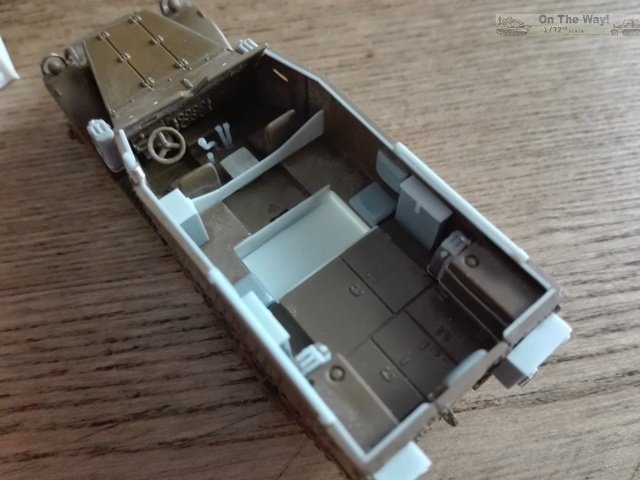
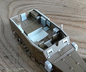
Dry fitting immediately revealed the fighting compartment was not deep enough and generally looks a bit bare of details. Some improvements were obviously needed.
I didn't over detail the kit and about the gun my job could look a bit approximate, but at the end the model looked detailed enough to me. I divided the model into
three sub assembly to ease painting.
Having them in the attic, I used two old books: US tank destroyers, Tank illustrated #19 and US half tracks of World War II, Osprey Vanguard #31, both by S.J.Zaloga.
I didn't find an M3 GMC walkaround on the net, but useful photos of a M3A1 APC are available at
militarymodelling.com.
A useful drawing is found at: motoburg.com.
Technical data can be found at the afvdb.
Below are the changes I made to my M3 GMC:
Hull Interior
- I engraved the inner doors lines.
- The upper hull edge should look thick. In actuallity it is thin, because along the edge there was an inverted L rod. To replicate this I glued a stretched sprue,
sanded flush to make the horizontal part.
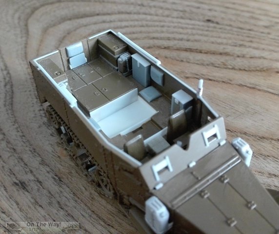
- The floor is raised too much. It is not a real problem in a war gaming point of view, but this interferes with the upper edge of the hull and the floor of the
fighting compartment. I cut it in four segments: one for the driving compartment and three for the fighting compartment. The part which falls in the driving
compartment was filed at the bottom and at the rear to allow it to be interlocked between the seats. To it I added the scratch built gear levers after having
drilled their holes. The forward fighting compartment, one is the gun base, which was left separate to be modified. The rear one was filed on the bottom to make it
1.5 mm lower. To the tanks I added the holders using thin metallic strips. The mid one was discarded. In its place, the fighting compartment floor was opened
as wide as the rear raised floor. The hole was closed by a new floor made with plastic sheet.
- Under the steering wheel I added the pedals made from plastic.
- Just behind the seats there is a shaped plate. I made it with plastic sheet, keeping it slightly spaced from the backrests.
- Between the seats there is a wireless box.
- I added the three seats of the fighting compartment made by shaped plastic pieces - two just forward the raised floor and the rear one attached to the door.
The back rest was fixed while the seat was hinged to be folded up (I made it in this way).
- I made the two bins located near the seats using plastic pieces and plastic sheet.
- Between these bins and the seats there are two jerrycans. I added taking them from the spare box.
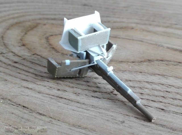
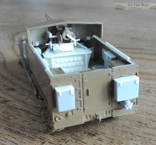
- On the gun support I glued a new shaped top and a new wall. To this I added the sides and the three rows of ammo, made with plastic sheet and rod thin segment.
It received also the triangular frame made with stretched sprue.
- Just behind the driver, another bin was made with plastic pieces.
Gun and shield
- The gun shield's inner side has a couple of ejector marks which were sanded. The lower slots were filled with pieces of plastic.
- The gun mount was hollowed with a motor tool. The rear and the front were made sloped and then closed using plastic sheet.
- To the gun mount's sides I filed away the details and then I added the aiming gears and the sight from stretched sprue. The aiming wheels are plastic
disks because my efforts to make them with spokes didn't have good results (PE after market parts would help here).
- The gun rear holed plate was carefully cut off. The gun rear was improved making it rounded and detailed with plastic strip and stretched sprue. The holed
plate was glued in place.
- Both ends of the gun were drilled open.
- The gun barrel support bottom section was triangular and not flat (as is the cut in the hull front plate). I modified it with plastic pieced shaped in place.
- Under it and on the mount I made the lock with stretched sprue segments.
- On the shield front I glued two stretched sprue segments after it was placed on the gun.
Hull


- On the bottom rear I replaced the interlock with a plastic piece of the same height where the chassis rear has to be glued. The hole was closed.
- The holes found on the bottom of the seats were closed with plastic.
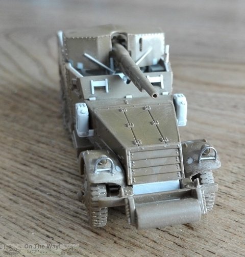
- The front cover has some sink marks. I removed them. The shutters on the vision slots are missing. I made them with plastic sheet and stretched sprue. I also
made the three hinges, which were placed at the bottom edge instead of the upper as in the other variants.
- I removed the moulded on jerrycans and replaced them with others from the spares box. The kit ones are too thin and placed incorrectly parallel to the walls
and not to the longitudinal axe of the vehicle. They were kept in place by a holder and a belt.
- On the bottom front I replaced the interlock with a plastic piece to simulate the radiator bottom. Another one was glued to make the sloped plate behind the
roller.
- The towing hook was drilled open.
- On the rear plate there are two external bins. I made them using pieces of plastic glued together and shaped.
- I added also an item which looks like a pail, with its straps. The pail was fashioned from a piece of sprue in a motor tool used as a lathe.
- On the upper edge there are two handrails. Stretched sprue and a couple of plastic shim did the job.
- Near the driver's position there was the flexible antenna base. I used stretched sprue and thin metallic wire to make it.
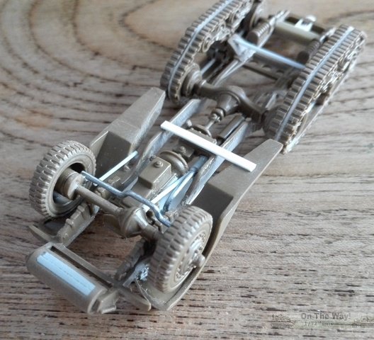
Chassis
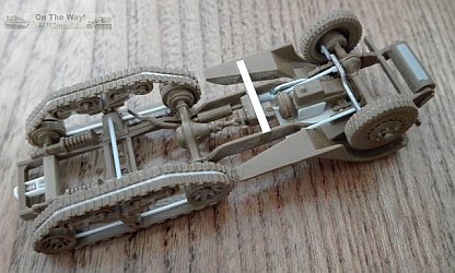

- The bottom of the front roller was filled with plastic pieces shaped in place.
- The rear frame square rod was replaced by a new one where there is the idler axle.
- A small segment of stretched sprue with wrapped around a thin metallic wire and a frame made by plastic sheet reproduced the hidden part of the towing point.
- I also removed the moulded on mid-axle which was replaced by a stretched sprue segment.
- Most of the forward floor was removed with a motor tool to give depth and to replace some moulded on details like the exhaust pipe and the transmission axles.
- I added also the steering gear by shaped metal wire and stretched sprue.
- After having erased it at the beginning, I replaced the transversal rod with a plastic strip segment.
- Production ended in April 1943 and the lamps were still of the fixed type. I filled the lamp's locating holes in the mudguards and then removed the bulge on the
underside with a motor tool. The lights were glued to a more central location on the mudguards.I scratchbuilt their brush guards (I made just the frame)
with stretched sprue and curved staples.
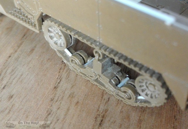
- The 8.25 x 20 wheels dimensions are quite correct (13.5 x 3.5 mm) and looked useful so I didn't try to further detail them.
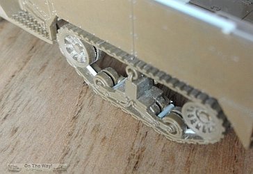
- The solid tracks needed at least some basic detailing. The tracks were continuous rubber bands with a metallic core. On the outer side the blocks weren't single,
but double, and on the inner side there was a guide rail. The wheels were paired. The sprockets and the idlers were very complicate pieces and their
correct reproduction is a challenge in the bigger 1/35 scale, let alone in our smaller 1/72.
To improve the tracks I thought that the first thing to do
was thin the outer edge using a piece of sand paper wrapped on a rounded rod. Then I used a saw to cut each track along the mould line, almost separating
them into two halves. After having cleaned the cut line, I pushed 1.0x0.5 mm plastic rod pieces into the slots and gluing with liquid cement. Doing this
created both the separation between the outer track blocks as well as the inner rail. Between the wheels pairs I used a motor tool to make room for the frame. In this
space I placed a stretched sprue segment. This job doesn't make a perfect replica of the tracks, but in my opinion makes it more likely.
- The exhaust pipe end was protected from excessive vibrations by a little plate, which I reproduced with plastic sheet.
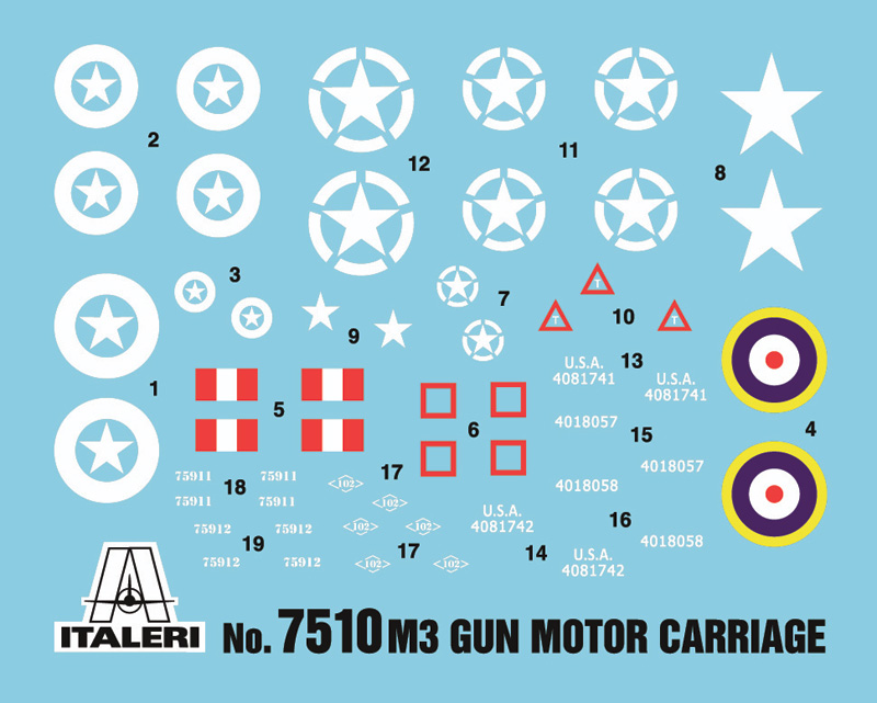
Decal
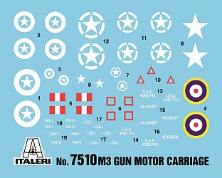
- The set is generic but very useful when used in conjunction with some spare decals.
- For the US Army markings there are four serial numbers: 4018057, 4018058, 4081741 and 4081742. The 40 prefix is correct for this class of vehicle, but the
only valid
serial numbers are 4018057 (see below) and 4018058, which fall within the 1350 M3 GMC batch numbered from 4017060 to 4018409. The serials 4081741 and 4081742 are not in
the M3 GMC batches. I don't have the full database of US serials, so I'm not able to say to which vehicle type they are associated. The set has eight US stars with
the full thick circle variant, eight of the type with a thin stencilled circle and another four without the circle. All are printed as pairs of different dimensions.
- For the British Army, two A1 type RAF roundels and four RAC red-white-red rectangles are given. There are also three red triangles and four red squares for A
and B Squadron of a Senior Regiment. There are no divisional badges or AoS numbers. No WD numbers are given, 4018057 (see above) is correctly placed on a
camouflaged GMC (IWM NA14653) which had the B Squadron square painted also inside the upper folding part of the door to make it visible when folded. The use of
US serial is not strange and also in a photo taken in 1945 in NWE, the 4053757 serial is sported by a 1st Royal Dragoons GMC. The WD numbers allocated to the M3
GMC were in the batch from F327959 to F328158, for 200 M3 Half Track 75mm SPG (on MAFVA site).
- The only non generic variant is about the U.S.M.C. 3rd Division in PTO. Decals for two vehicles are given: 75911 and 75912 (which should be U.S.M.C. serials)
associated to the rhomboid outline with 102 inside. The marking are correct for 75911, although no marking are depicted for the rear in the instruction. I didn't
have info about the leathernecks, but just to give a more complete info, I did a little research. As far as I found, the 3rd Div had a vertical lozenge, but to avoid
a too large marking (it should have the three digit number within) it was carried horizontal, like the 1st Division one. The number 102 should be read as follows:
1 = 1st Regiment, 0 = a unit attached to the Regiment not under a Battalion (the second digit was the Battalion), 2 = 2nd Company. In the photo of 75911 just over
the 0 seen there is what looks to be a very small 3; as far as I've found it was added to differentiate the 3rd to the 1st Division.
Conclusions
Making an M3 GMC with the kit required some generic improvements which can be avoided mating the specific parts with a good M3 APC display kit, such as the Academy
M3A1. Not loving waste, I used the whole kit, but everybody can make its own choice. At the end, the half track body is generally correct and worth the improvement
job to have a display model. I think this kit is interesting to be used alone or as aftermarket kit. For war gaming it is certainly good as it is.
Review sample purchased by the author.
Italeri products are available at

|