| This
is one of the more British style vehicles one can see in a WW2 photo.
For a long time, the only way to have a Universal Carrier in small
scale plastic kit was modeling the Airfix HO/OO kit, which is even
smaller than 1/76 and needs a lot of work.
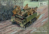
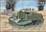
In recent years the IBG kits filled this gap with no less than four
very well done kits, each one being a different variant (Mk I, Mk
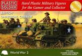
II, Mortar carrier Mk II and Boys AT Mk I). PSC arrived with a quick
building kit, which reflects the philosophy to have multiple simplified
models. Three Carriers are given without decal set. It is a cheap
and simple solution.
In my opinion the only really negative point shared by both manufacturers
could be about the wall thickness (but to have them in the right scale
they should be done with PE parts). Anyway on the later production
the problem is felt only in the driver compartment because the rear
compartment had a rounded handrail to protect the crew from the edge.
Thinning them is not as easy as one can think. If correctly thinned
the finished interior would have spacing at the engine cover and the
compartments division endings. Moreover if the plates are replaced
with thin plastic sheet the tiny surface details would be lost. If
the plates are thinned only on the upper edge, the finished look would
not be as good as one may wish, with a triangular section well visible
in the corners. At the end I kept them as they are (for both IBG and
PSC).
The PSC kit gives us the parts to make both Mk Is and Mk IIs, but
doesn’t have the towing hook.
About that, I found a bit confusing fact. Most of the sources I consulted
states the Mk II had the towing hook while the Mk I didn’t.
Anyway I found some photos of Mk IIs without the towing hook (and
few photo of Mk I with the hook, like T79484 or Mortar CT163736).
It means PSC is not exactly wrong for this.
On the other hand, in a 1/72 perspective the main differences we can
list between the two Marks are about:
- The
different mudguards skirts
- The
different front lights layout
- The
different stowage bin on the rear plate
The Mk
I rounded bent mudguard skirts were associated to the double lamps,
but already in the Mk I batch CT199801-CT201800 there are Carriers
which shows the later single lamp at left. Also T132812, a Mk I Mortar
carrier of the T132736-T133149 batch, had this lights layout, but
I don’t have other photos of this batch. The Mk II squared stiffened
skirts were used at least by the T202177 - T203776 batch onwards.
I don’t have a photo of a Mortar Carrier of the CT201801 - CT202100
batch, which could be based on the last Mk Is or on the first Mk IIs.
Dimensions of the assembled kits are quite correct and the comparison
between the 1/72 kits reveals they are very similar:
|
|
1/72 |
PSC |
IBG |
Length |
12ft
|
50.8mm |
50.1mm |
51.4mm |
Width |
6ft
9in |
28.6mm |
27.2mm |
27.2mm |
Height |
5ft
2in |
21.9mm |
21.0mm |
20.3mm |
And if
someone is wondering about the Airfix kit:
|
|
1/76 |
Airfix |
Length |
12ft
|
48.0mm |
47.1mm |
Width |
6ft
9in |
27.0mm |
25.0mm |
Height |
5ft
2in |
20.7mm |
18.6mm |
To make
my models I had to try to understand a bit more about the Universal
Carrier variants (ignoring the former Carrier types as well as the
overseas production types) because 113,000 were produced and some
differences were made along the production. What I’ve found
is that the little Carrier tree had more branches one can imagine.
Again I had some difficulties to understand the British nomenclature,
also because there are some little differences between one source
and another.
The Universal Carrier was made in three Marks: I, II and III. A number
before “Mk” means the engine type: No.1 (65 hp), No. 2
(85 hp), No. 2A (85 hp) and No. 3 (95 hp). A star (for example No.
3 Mk II*) meant a Canadian built carrier.
It should be simple, but I didn’t understand if each Mark was
produced with every engine type: the cover of the April 1944 Service
instruction book (photo found on MLU forum), shows only the following
types:
- Carrier,
Universal Mk I
- Carrier,
Universal No. 1, Mk II
- Carrier,
Universal No. 2, Mk I and Mk II
- Carrier,
Universal No. 3, Mk II
Aside
the Universal configuration, there were three official variants: the
Carrier, Armoured, Observation Post; the Carrier, 3” Mortar
and the Carrier, Medium Machine Gun.
Always referring to the April 1944 Service instruction book, the list
is about:
- Carrier,
3” Mortar No. 1, Mk I and Mk II
- Carrier,
3” Mortar No. 2, Mk II
- Carrier,
3” Mortar No. 3, Mk II
- Carrier,
Armoured, Observation Post No. 1, Mk I, Mk II and Mk III
On this
cover (I don’t have the book) the Mk III is referred only to
the AOP variant, but in other sources the Mk III is referred also
to the Universal carrier type. Although some sources I found say that
starting from the Mk II the hull was welded, I think this could refer
to the lower hull, because photos clearly show the riveting on the
upper hull sides, at least for the following batches: T202177 - T203776,
T208740 - T210400, T223384 - T223983, T226038 - T228466, T252505 -
T253123, T274035 - T274648, T275608 - T276638. I didn’t find
a photo of a Mk II with the welded upper hull. The kit plates are
riveted; as far as one can correctly expect, the inner sides should
show the inner structure of bolted “L” rods which keeps
the whole together, but they are completely flat and no details are
given by both kit makers.
The welded hull was certainly used by the Mk III. In the April 1944
Service instruction book the welded Mk III is called Mk IIIw (such
as for the Cromwell Mk Vw). In the MAFVA census number list, there
are only one UC and two AOP batches named as Mk III. The UC T331701
- T334900 batch was cancelled and not produced (“Universal carrier
1936-1948” by D. Fletcher) while two other batches ordered as
Mk II (T272101 - T272884 and T339801 - T340408) were produced as Mk
III. On the basis of the differences found from the former marks,
the Mk III had a new engine cover with a different air inlet and a
new transversal division plain plate (which is more visible in photos)
without the large rectangular slots just above the forward seats.
If this is the rule, also the batch T245780 - T249540 which is identified
as Mk II in the MAFVA list should be Mk III. The batches produced
as UC were made when the standard was the Mk II, so they had the same
skirts, lamp and rear bin. The AOPs were made when the standard was
the Mk I and had the same skirts and rear bin while a single lamp
was placed on the glacis.
Speaking about how to have something a little more different, apart
fom the production wheels with narrow “T” section spokes,
I’ve seen two variations. A first variation had a concave plain
centre with six large rounded holes (see for example T274089 or T253118);
the second one had larger spokes (see for example CT43325 or T202226).
As far as I’ve seen up till now these two types look to be used
as replacement and not as production line set.
I didn’t study the early production Carriers in detail, so it
is possible that I ignored some details or that some comments about
them are not pertinent.
Other minor layout differences look to be given by the crew role;
see here: http://www.vickersmachinegun.org.uk/transport-universal.htm
.
To add other modelling possibilities, home made bins or racks or arrangement
alteration added at the unit workshops can be seen in the original
photos, see for example the airborne Universal Carriers.
Also the Russians lend-lease vehicle and the German captured Carriers
give us opportunities to model different subjects. For some useful
Beute Bren Carrier (e) photos see here.
Speaking
about some reference on the web between others, a couple of useful
walkaround are here:
A useful
information source can be found here.
And useful photos here.
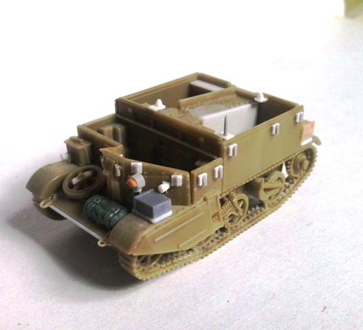
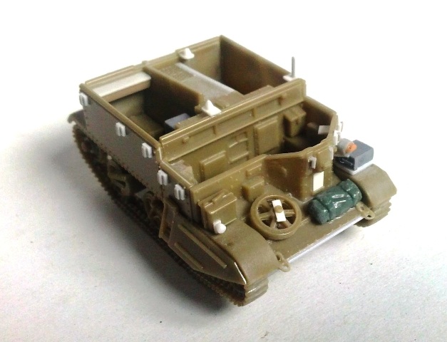
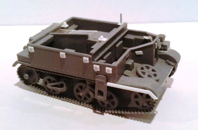
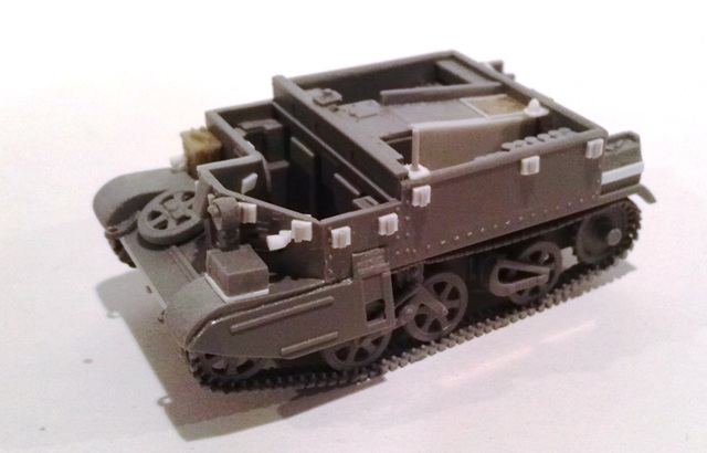
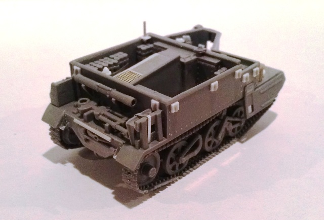
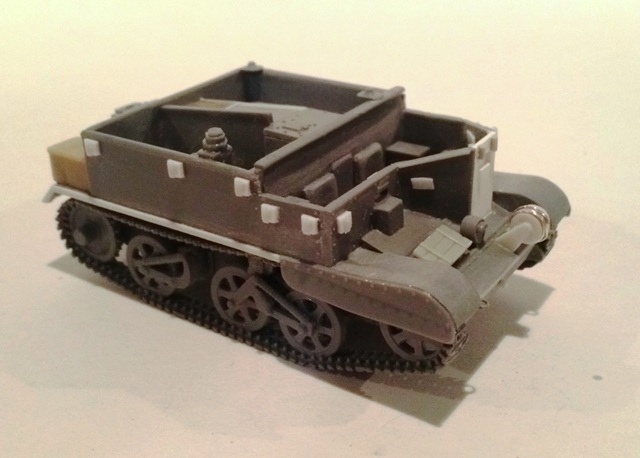
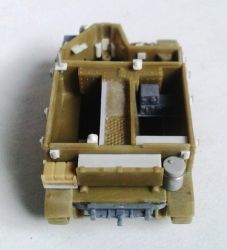
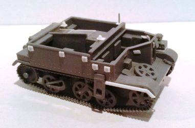
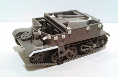
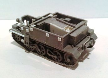
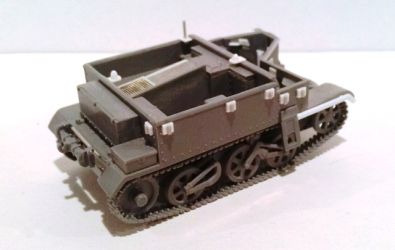
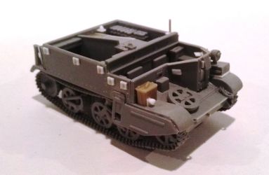
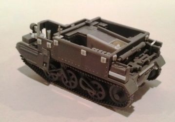
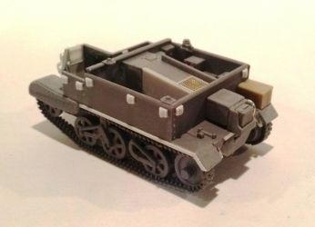
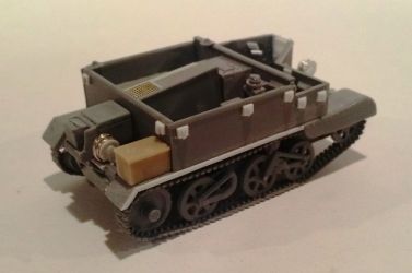
The
PSC kit
The look
of the mouldings gives a sober impression, only 27 pieces composes
the vehicle set (comprising the optional parts and the large roll);
some details are not very finely sculpted and the wheels and tracks
sets are solid single pieces.
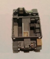
Coming from the war games world, this kit has the crew (very well!).
The two figures for the driving compartment are a bit stiff, while
the rear compartment figures relaxed pose are more convincing, however
they are moulded for a Carrier stripped of the usual items stowed
in the rear compartments. The heads are given as separate parts. This
is positive: the faces are moulded from the front; the head can be
slightly turned and can be easily swapped. The PSC heads look to me
too much near the chest so I shimmed the neck a little.
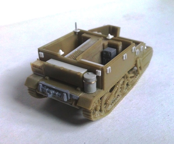
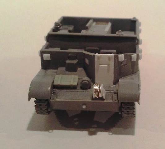
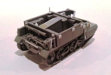
I added some basic details to my kit. Here is what I did to have a
Universal Carrier Mk II in Normandy:
Hull
- The
poorest detail of this model is the solid over simplified exhaust
area. I filed away the “box” with the moulded on the
transmission axle which fills the area, keeping just the differential
housing. I closed the wall with thin plastic sheet and then I added
the details. The axle was made with plastic rod while the exhausts
were made with stretched sprue.
- I
drilled the holes in the front towing points moulded on the glacis,
which were also thinned.
- I
thinned the exposed fender thickness.
- The
mudguard skirts were sometimes removed, but the tracks miss their
external details where the skirts have to be glued making their
use compulsory.
- The
hole for the Bren gun could be closed with a simple rectangle when
the gun wasn’t used. If the Bren is to be installed, a replacement
is recommended.
- The
spare wheel could be fixed with a large roundel as for the kit,
or with a little rectangular shaped plate. I changed it but the
kit detail can be kept as it is.
- The
Mk II rear bin was heightened with thin plastic sheet.
- Mk
II sides could have two further steps just in the mid of the rear
compartment. The kit doesn’t give them, but this is not a
problem because they don’t look to have been widely used.
- The
Mk II single light is huge. I replaced it with a scratchbuilt one
made with sprue sections and then I detailed it with its support
and its thin metallic wire.
- On
the front there also were smaller lights; they were added (with
their supports) using plastic rod shaped as a half egg.
- A
simple improvement can be made adding the deep wading kit interlocks.
These were thick rectangular plates, with a pipe segment welded
on and bolted to the hull sides. I made them with plastic and stretched
sprue. The full deep wading kit is quite easy to scratchbuild and
is a good way to have something different from the models proposed
by the manufacturer added an IBG towing hook which was in the spares
box. As already seen, its absence is not really a problem.
- On
the front plate there was a short horizontal closed pipe. It was
access for the starting handle. I drilled the hole where it will
be glued after the driver compartment will be closed because the
upper millimeter of the plate is the glacis thickness and the surface
will be sanded smooth.
- The
glacis overhangs the front plate a little. I added this with a thin
stretched sprue segment.
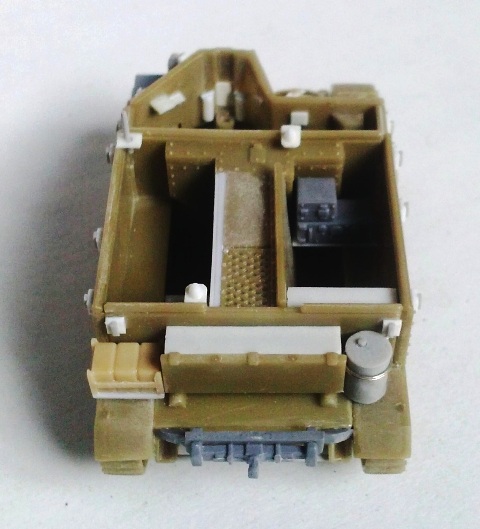
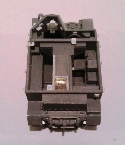
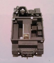
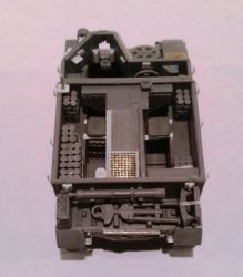
Interiors
- In
the photos I’ve seen the left side of the engine cover was
vertical. To correct this I placed a new side widening the kit deck
at left. This means I lost the riveting row. I’m not so clever
to make a new one.
- I
made the instrument panel with a piece of plastic from the thick
squared sprue.
- I
also added the inner shutters of the vision slots made with very
thin plastic sheet.
- The
inside is very empty. Some bins and some boxes are needed to fill
the driving and the rear compartments. Inspiration was found in
photos.
- I
also added the shelves for the antenna bases.
- I
also added an IBG wireless apparatus left from the mortar carrier
kit
- With
plastic rods I made the two fire extinguishers. They were of the
brass colour types which were placed at the sides of the Bren gun
mount (the handle was “T” shaped but after having had
a nervous collapse I left it alone as you can see. I know, the vertical
arm is missing).
- Also
the support for the Bren gun was made with plastic.
- In
the co-driver area I added the shelf for the 2” mortar.
- The
seats are missing in both compartment, I didn’t add them because
I planned to use the crew. About that, I added the legs to the driver.
- After
painting I’ll add the Bren gun and the Enfield rifles taken
from the spare box. The former will be stowed between the driver’s
compartment seats; the latter in the rear compartment.
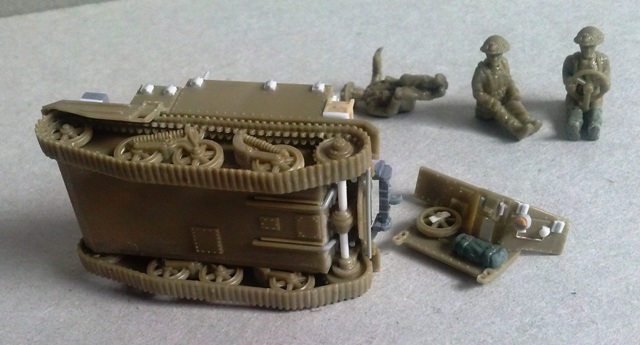
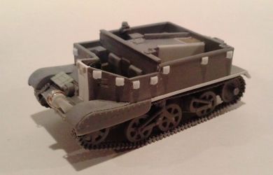
Wheels
and tracks
- The
double guide teeth are solid. As for my S-Model Stuart tank, the
solid tracks were cut in sections and glued in place after having
divided the guide teeth with a file.
- Having
cut the track units in sections, I drilled the solid parts between
the bogey suspension springs before re-assembling them. Looking
at the photos while editing the review, now I think that a better
result could be obtained with thin metallic wire wrapped around
a stretched sprue segment. Too late…
 
 
Thanks
to Gianluca Trivero who shared one of his three kits in the box.
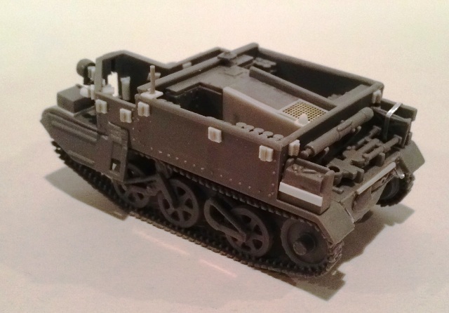
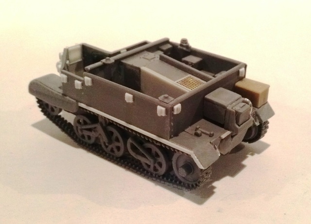
The IBG kits
These
kits need very few words to describe. When I saw the photos of the
mouldings for the first time I thought I was seeing 1/35 kits! Very
well detailed, this kit can almost be built straight out of the box.
Some details thickness look a bit oversized, but still look well.
A bit hard to achieve is a correct track assembly. I didn’t
use the template present in the box. The interior is well detailed
and a lot of items are given to fill the compartments.
Very little work was needed to have two carriers in Normandy: a Mk
II and a Mortar Mk II. About the latter, an easy conversion can be
obtained making the Mortar Mk I swapping the specific pieces. A specific
job was made to the mortar base, which lower side details need to
be thinned (the thickness on the edge and the blades which go in the
ground). I added some basic details:
Hull
- The
glacis overhangs the front plate a little. I made this with a thin
stretched sprue segment.
- As
already told, I chose to ignore the wall thickness, but the rear
compartment handrail is squared, which is not completely wrong.
It was used squared on the early production Mk I. I sanded it rounded.
- On
the front plate I added the starting handle access with a stretched
sprue segment.
- The
front towing points are plain and too thick. I drilled the holes
and thinned them before gluing on the glacis. Attention must be
paid because they are not identical and are not interchangeable.
- The
right side of the MG position had a narrow strip welded on the edge.
Also this was made with a thin stretched sprue segment. PSC has
this detail moulded on.
- Just
under this segment I added a little thin plastic trapezoid. It is
the shutter of a vision slot, missing in the kit.
- I
thinned the exposed fenders.
- The
Mk II single light received its wiring.
- I
also added the little lamps present on the Mk II front.
- The
Mk II skirts upper edge doesn’t have the gap and doesn’t
look well. I reshaped it and thinned the edges on my Mortar carrier.
To have something a bit different I made the Mk II without the skirts;
the exposed edge of the mudguards was made with thin plastic strips.
The steps in the skirts were sanded on the upper part, which were
not flat.
- The
rear steps are small and solid. I replaced them with thin metal
strips folded and cut to the shape.
- Also
my IBG carriers received the deep wading interlocks. On the UC two
of them are missing because they are placed where I have to glue
a couple of crew items.
Interiors
- As
for the PSC kit (see above) I corrected the engine cover. Here too
I lost the riveting row.
- On
the widened deck I had to add a new mesh, which is not a bad thing,
because IBG didn’t do a good job in depicting it. (Take a
look with a magnifier.)
- I
also added the inner shutters of the vision slots made with very
thin plastic sheet.
- I
added the missing shelves for the antenna bases because these small
parts can easily be lost.
- With
plastic round rods I made the two fire extinguishers of the “early”
brass cylinder type which were placed at the sides of the Bren gun
mount (these too with the handle not “T” shaped).
- In
the co-driver area I added the shelf for the 2” mortar.
- I
softened the corners of the padded seats
- I’ll
add the stowed Bren gun and Enfield rifles after having painted
the interiors.
- The
raised strip on the deck is too thick; the best thing to do is replace
it… I kept it as it is.
Wheels and tracks
- The
links pitch should be tighter. The effect is that they look too
much spaced. Anyway the tracks look well and I kept them as they
are, but for who is more finicky an aftermarket set is available.
- In
my kits the wheels spokes were almost joined by the (thin) flash
of the mould. I carefully cleaned them before I cut them off from
the sprue.
- A
careful job is needed to cut off the sprockets because the presence
of the sprue between the little sized teeth.
- I
didn’t use the template for the tracks, preferring to glue
them directly on the wheels set, adding a little sag on the upper
length.
Universal
Carrier:
Mortar
Carrier:
An
easy conversion: the AOP Mk III
I wished
to also have a Carrier with the Mk I skirts. As far as I’ve
seen up till now, with the British troops in Normandy the UC Mk Is
were rare. The Universal Carrier Mk Is looks to be more widely used
by the Canadian troops. For mine I opted for an AOP Mk III (the AOP
Mk I was based on the earlier Scout Mk I and the AOP Mk II on the
UC Mk I), although the Mortar Carriers Mk I (see for example T80222
or T167648) were used as well.
As far as I found 4,577 AOP Mk IIIs were made in two batches (T84621
- T88063 and T167832 - T168965). Photos taken in Normandy show the
usual deep wading kit, the absence of the ladder on the left side
and the inner antenna shelf. The AOPs were used not only by the Artillery
unit; they were also used by the Infantry units, as witnessed by the
AoS numbers. To make mine I made the same job already described above
and then:
- The
main difference between the other marks was in the engine cover,
which had a different air inlet layout. The “V” shaped
part was cut off and the holes closed with plastic.
- The
air inlet on the division plate were erased and the hint left at
the end filled with cyanoacrylate glue which fill very well the
little sinks.
- The
Mk III had a welded hull, so I erased the riveting.
- An
easy way to recognize a welded hull in low definition photos (were
the riveting is not well visible) is the raised lower edge of the
upper side plates. A simple plastic strip did the job.
- The
skirts are well done and need only to be thinned. If these are not
used the mudguards edge is correct as it is.
- As
far as I can tell, the Mk I rear bin is a millimeter too long and
the rack a millimeter too short. I shifted the engraving forward
and thinned the rack.
- The
Bren gun position was closed with a new flat plate, where I cut
the window. This was closeable with a sliding plate which could
lifted to see through.
- I
replaced the double lamps with a late type single one placed in
the middle of the glacis.
- Photographic
evidences shows the absence of the spare wheel on the glacis. Its
place was often used for boxes or soft items.On the rear shelf right
side and on the glacis there were two cable reels. I made them with
plastic and thin metallic wire.
- I
suppose there were other little differences, but I was satisfied
and I didn’t add other.
Decal
When I bought my kits, there were only two out of four kits in the
shop of my town: the Mk I w/ Boys rifle and the Mortar Carrier Mk
II. They were pretty good for my needs.
- Mk
I T78987, Red Army. It is correctly depicted.
- Mk
I CT112308, Loyal Edmonton Regt., 2nd Inf. Bde., 1st Cdn Inf. Div..
It is correctly depicted, the right light is missing and its place
is taken by a metallic box. The AoS number on the front is symmetrically
placed to the Divisional badge, the Boys rifle is not on the firing
position.
- Mk
I No WD Beute carrier. It is correctly depicted, but looks to be
unarmed.
- About
the following I didn’t find their photos:
-
Mk I T8873, 10th Pol Mounted Rifle Regt., 1st Pol AD. The WD
number is for a Mortar carrier Mk I
-
Mk I CT43054, 7th Recce Regt., 3rd Cdn Inf. Div., .
-
Mk I T17068, 5th Royal Hampshire Reg., 128th IB, 46th ID. The
suggested WD number falls in a Beaverette batch. Anyway, it
is only suggested in the instruction, being absent in the set.
- Mortar
carrier CT201944, 43rd Infantry Division, 43rd Recce Regiment.
If correctly depicted by IBG, this should be the first batch
based on the Mk II hull in the WD number sequence.
-
Mortar carrier T228174, 25th Uhlan Polish Regiment, 5th Polish
Infantry Regiment. The bison on a yellow background looks like
the badge of the 11th Armoured Division. The 25th Ulanow Wielkopolskich
was a Recce Regiment; the blue/green background is correct as
well as number 77.
Kit purchased
by author.
Conclusion
The comparison
between the kit makers doesn’t give us a winner. IBG kits, despite
their faults, are still great and look well with very little extra
detailing. As a wargamer kit the PSC kit is very good, simplified
but correct. A feature shared by both kit makers is the engine cover
section which is symmetrically sloped. I didn’t find photos
which show this engine cover type and I don’t know if it was
really used; anyway I modified it for my models to a type that is
surely correct. Surprisingly, some PSC details are better depicted,
like the rear steps, the engine deck mesh, the Mk II skirts and the
gunner position plates. For both, an aftermarket set with the engine
cover, PE upper hull plates and other little details would be useful.
The kits also offer a good base for easy conversions which only need
some plastic sheets and rods. At the end I think that the IBG kit
is certainly better detailed, but if your model is packed with different
sorts of stowage which hide the details and has a crew, the PSC kit
is, with a little elbow grease, a very good alternative.
IBG & PSC products
are available at

|