| Introduction
I started
building the Dragon Nashorn after finishing the Revell Nashorn, in
order to compare both kits from different manufacturers. Somewhere
during the construction of the Dragon Nashorn, I realized that I hadn’t
chosen the optimal approach and had been rather sloppy in places,
even though I was following the instructions. In hindsight, I could
have planned the build more carefully and achieved a better result.
That’s why I started building the almost identical Dragon Hornisse
in parallel: to learn from my mistakes and to share those lessons
with our readers. For that reason, I will explain how I built the
Nashorn and afterwards how I tried to improve the process with the
Hornisse. For the latter, I will only point out the differences in
approach.
Version
The Dragon Nashorn kit has the features of a Nashorn built from May
1943 onwards. In that respect it is almost identical to Revell
kit 03148.
The only difference that I spotted was that the Dragon kit offers
both early and late drive sprockets, which can be correctly combined
with the other features of the kit. However, the instructions don’t
tell you which marking option uses which drive sprocket, so checking
photographic references is recommended.
The extra radio in the fighting compartment is probably indicative
of a Befehls (command) vehicle and would thus be an optional feature,
something Dragon doesn’t specify, even though it mentions the
extra antenna and MG swivel mount as optional. (See more about that
below.)
The Dragon
Hornisse kit has the features of a March 1943 production vehicle.
See the review of the Revell
kit for details.
In this kit, the instructions mark the extra radio and extra antenna
as optional, but not the MG swivel mount. As the swivel mount is close
to the radio, this might indicate an error in the instructions for
the Nashorn.
Instructions
_t.jpg) _t.jpg) _t.jpg)
Pictures from Henk
of Holland website, used with permission.
_t.jpg) _t.jpg) _t.jpg)
Pictures from Henk
of Holland website, used with permission.
_t.jpg) _t.jpg)
Scans of the sides of the box of the Nashorn kit
_t.jpg) _t.jpg)
Scans
of the sides of the box of the Hornisse kit
A comparison
of the sprues of both kits can be found here.
Note
that both kits were later re-released with "NEO" tracks.
- Kit
7626 - Sd.Kfz.164 Nashorn w/NEO Track
- Kit
7625 - Sd.Kfz.164 Hornisse w/NEO Track
Construction
The
hull (Nashorn):
_t.jpg) _t.jpg)
Various stages of assembly
The
hull (Hornisse – differences with respect to the Nashorn):
- The
V-shaped depression on the glacis was filled in before the part
was added to the hull. This was still a delicate operation, but
much easier than doing it after assembly.
_t.jpg) _t.jpg) _t.jpg)
New approach to fix the the V-shaped depression and
removal of remnants of the release mechanism
- I
used the kit-supplied DS tracks for this build, so didn’t
need to modify the spare track holder. More about those later, though.
- I
took much more care with Parts C1 and C2. It helps if you bevel
the rear of Part C2 a bit.
This time, no tedious remedial action was needed.
_t.jpg) _t.jpg)
Different assembly sequence compared with Nashorn
- The
tow hooks at the rear of the hull were removed as per the instructions.
I believe Dragon could have given us a hull without tow hooks and
provided separate tow hooks for the kit that needed it (i.e. the
Nashorn), instead of requiring us to remove them.
- To
avoid the issues I had with the Nashorn kit, I built up the armor
plates for the fighting compartment, starting with the front, and
placing the side plates a bit higher this time, to create the distinctive
step.
- I
removed between 0.5 and 0.75 mm from the bottom front armor plates
of the fighting compartment so that the cut outs touched the roof.
I also beveled the bottom, to make them fit the fenders better.
As expected, this resulted in front armor plates (C14 and C15) that
sat lower than the side armor. (It also didn’t help that I
had already removed some material from the bottom of C14 and C15.)
I added a strip of plastic to the top of the front plates after
installing them. In hindsight, I should have done that before installing
them. It would have made it more difficult to match the correct
height, but it would have been easier to sand.
It might have been even easier to add a strip of plastic to the
cut-outs before installing C14 and C15. Perhaps next time.
_t.jpg) _t.jpg)
Different assembly sequence
_t.jpg)
The height different between front and side plates
is clear
_t.jpg)
Material added to the top of the front plates. The
lifting hooks on top of them now actually sit a bit too low
- I
noticed that the inside of the radiators within the side plates
interfered with the fenders. Some scraping solved the issue.
- I
installed the upper rear plate before fitting the lower rear plate,
to make sure it aligned well with the sidewalls.
_t.jpg)
Different assembly sequence
Installing
the upper rear plate first, required me to place the lower rear
plate a millimeter lower and remove excess plastic at the bottom.
I noticed that the triangular supports for the tow hooks still
wouldn’t line up, but as this kit doesn’t need the
tow hooks, it also doesn’t need the supports. Interestingly,
Dragon doesn’t tell us to remove them.
_t.jpg) _t.jpg)
Different assembly sequence. Material needs to
be removed at the bottom of the lower rear hull plate, but this
is not that difficult.
- I
didn’t damage the lifting hooks on the outside of fighting
compartment walls this time, but still removed the ones at the lower
edge of the fighting compartment.
- For
the Hornisse, there wasn’t a release mechanism for the barrel
lock, so the recess at the rear of the splash guard (C22) doesn’t
need to be drilled out. However, part of the release mechanism is
still present on the glacis part and should be removed, which Dragon
fails to mention.
- The
jack for this build was damaged and repaired.
- Note
that the supports for the barrel lock are different from those in
the Nashorn. However, Dragon doesn’t point out that the Nashorn
parts (C19) are “not for use”. D10 are the parts that
you need to use.
- I
broke the barrel during the build, but believe the fix doesn’t
really show. Speaking of which, I suspect that support E4 should
go where support E5 is shown and vice versa.
- It
took me a while to figure out what Part D3 was. It’s not mentioned
in the instructions. I believe it is a protective plate to ease
access to the fighting compartment over the (hot) muffler.
Fighting
compartment interior (Nashorn):
Fighting
compartment interior (Hornisse – differences with respect to
the Nashorn):
Running
gear (Nashorn)
Preliminary
note: Most of the issues with the running gear were only discovered
when it was almost completely finished, meaning that I had to disassemble
most of it to be able to perform the necessary modifications. I also
decided to use the MACO
Ostketten on this kit. Ostketten are rare for a Nashorn, but I
found one picture (below) that intrigues me. The DS tracks were badly
warped anyway. More about them below.
The things that I discovered:
- You
get an early and late drive sprocket. The instructions let you choose,
but all the marking options show the latter. Nevertheless, check
your references (and the discussion below) to make sure you choose
the right option.
- It
is difficult to align the bogeys due to play in the parts. The bogeys
are handed, but the instructions don’t tell you if Part e4
(or e5 for that matter) goes right or left. Take a close look at
Step 2 to make sure.
- Dragon
offers separate hubcaps, which is helpful when painting the road
wheels. My kit came with more hubcaps than needed, and more than
mentioned in the instructions.
- Some
hubcaps also have a deeper depression where the axle goes than others.
- All
hubcaps are of the early, cast type, which is correct for most vehicles
offered in this kit.
- The
holders for the spare road wheels on the back of the vehicle are
made from metal wire and nicely pre-bent to shape.
- There
is a small casting deficiency on the drive sprockets.
- I
shortened the axle of the rear return rollers to fit the recess
that was blanked off in the fighting compartment.
- The
MACO tracks come as individual links and short sections and while
they are nicely cast, they are a pain to assemble as the large number
of short sections doesn’t help with alignment. The recesses
also don’t line up exactly with the teeth of the Dragon drive
sprocket making partial removal of the latter necessary to ensure
a correct fit.
- There
are two main issues with this kit, however. The first is that you
need to move the drive sprocket, idler and road wheels inwards,
to have the tracks align with the return rollers and fenders. In
this kit this was done after assembling everything a first time,
thus creating one fine mess.
- The
second issue is that the road wheels themselves almost touch each
other. This throws off the look of the kit.
- There
is a swivel arm for the idler that comes as a separate part. In
reality this was used for track tensioning and in a kit it can serve
the same purpose, avoiding to and up with a track run that is not
a partial track too short/long. However, due to the alignment issues
mentioned above, not much of this swivel arm was left after surgery.
Running
gear (Hornisse – differences with respect to the Nashorn)
- Forewarned,
I removed material from the sides of the hull before assembly so
that idler, road wheels and drive sprocket sit closer to the hull.
It is quite an amount that needs to be removed, especially for the
drive sprocket (around 1mm).
_t.jpg) _t.jpg)
- As
the Revell
Nashorn road wheels are slightly smaller (6.45mm in diameter)
than those in the Dragon kit (6.70mm) , I decided to use the former
to create a bit more breathing room between the road wheels. (See
pictures below to see if you can spot the difference.) It only helps
a little. As the size of the Revell road wheels is fairly accurate,
I am starting to wonder if the entire Dragon hull isn’t too
short.
- In
this kit, I decided to use the Dragon supplied DS tracks. Between
my Nashorn and Hornisse kit I had two tracks that weren’t
warped beyond recognition and seemed usable. However, the tracks
turned out to be too short to go around the running gear, even with
the idler in the foremost position. As I had two spare tracks from
the Nashorn build with some unwarped sections, and as I was going
to put the vehicle on a diorama base, I could fix this by adding
the necessary length to the bottom. It was actually easier than
I anticipated.
_t.jpg) _t.jpg)
Painting
I normally do not comment on painting, but I noticed that the geometry
of the Nashorn, with all its nooks and crannies resulted in half-dried
(enamel) paint ending up almost everywhere, and especially where it
is difficult to sand, resulting in a very rough texture in my paint
job. For the Hornisse I decided to paint subassemblies first, which
resulted in a far better overall paintjob.
Markings
(Nashorn)
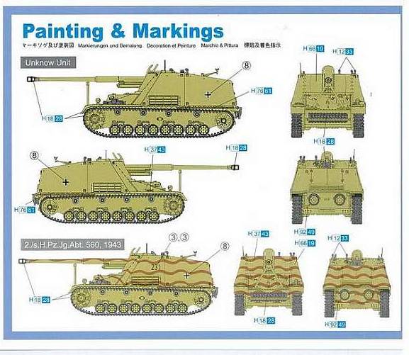
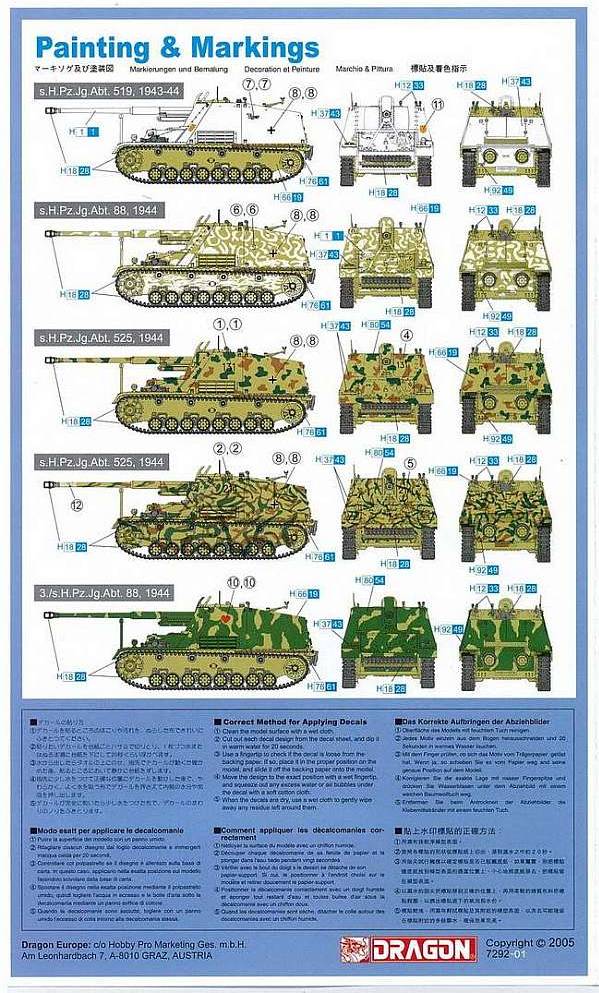
The kit offers markings for seven vehicles:
Pictures
from Henk
of Holland website, used with permission.
- A
plain yellow one from an “unknown unit”, devoid of any
markings except for the Balkenkreuze.
- “231”
from 2./s.H.Pz.Jg.Abt.560 in 1943. A picture of “231”
on page 35 of [1] (with matching camouflage pattern) shows it on
a train. While the vehicle can only be seen partially, it shows
rear mud flaps, indicating that it is most likely an earlier production
variant than what the kit offers. Other vehicles on the same train
are also early vehicles, some of which show appliqué armor,
a box on the right fender, spare roadwheels in the early position
and modified (early) mufflers. Based on pictures in [1] it seems
that vehicles of 2./s.H.Pz.Jg.Abt.560 often didn’t carry any
MG on the swivel mount that Dragon offers, or had it in a different
position. Also, see the discussion below.
- A
whitewashed vehicle (“Tiger”) from s.H.Pz.Jg.Abt.519
in the winter of 1943-1944. This is a sister vehicle to the one
in the Revell
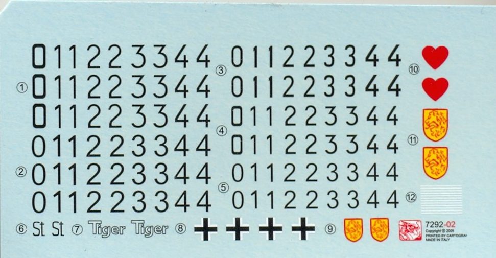
kit. At least Dragon offers the unit badges, although pictures
in [1] would suggest that a smaller badge (decal 9) was carried
at the front (Dragon suggests the larger decal 11) and a larger
(decal 11) at the right rear (where Dragon doesn’t put anything).
The unit is also known to have added a spare roadwheel to the side
of the driver’s compartment, which is confirmed by a picture
of this vehicle on page 43 of [1]. The unit also often added logs
to the bow, which the kit doesn’t provide. For a representation
of this marking I refer to the construction review of the Revell
kit.
- A
white/yellow vehicle from s.H.Pz.Jg.Abt.88 in 1944. Worthy of note
is that this unit often fitted a MG42 on top of the main gun, which
the kit doesn’t provide. This unit is also known to have used
playing card symbols to denote companies. While marking option 7
takes this into account, this marking option doesn’t. However,
based on the picture on page 45 of [1] this seems to be correct.
- “131”,
a three-color vehicle from s.H.Pz.Jg.Abt.525 in 1944. This is probably
the vehicle on page 39 of [1]. The unit is also known to have added
a spare roadwheel to the side of the driver’s compartment
which the kit doesn’t provide and which seems to be correct
for this particular vehicle. The unit often also repeated the tactical
umber on the gun shield, which the kit provides.
- “214”,
a three-color vehicle from s.H.Pz.Jg.Abt.525 in 1944. Same remark
regarding the extra roadwheel and tactical number. I didn’t
find a picture of this particular vehicle.
- A
yellow and green vehicle from 3/s.H.Pz.Jg.Abt.88 in 1944. This unit
used playing cards to denote its companies and often fitted an MG42
on top of the main gun, which the kit doesn’t provide. If
the vehicle is the one on page 46 in [1] this seems to be correct.
If the vehicle shown on page 30 and in the color profiles in [1]
is indeed also from s.H.Pz.Jg.Abt.88, then this unit might additionally
have used tactical numbers on the rear of the fighting compartment,
which the kit doesn’t offer.
Of the above, it seems that inspiration for 4 of the marking options
are taken from color profiles in [1].
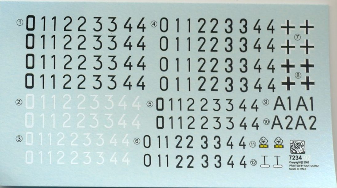
The kit offers spare decals and individual numbers in different styles.
I built my kit loosely based on a picture on page 30 of [1] (also
to be found here),
showing a vehicle without markings and equipped with Ostketten.
_t.jpg) _t.jpg)
 _t.jpg)
The vehicle was put in a diorama, using figures and accessories from
Tracks and Troops.
Markings
(Hornisse)
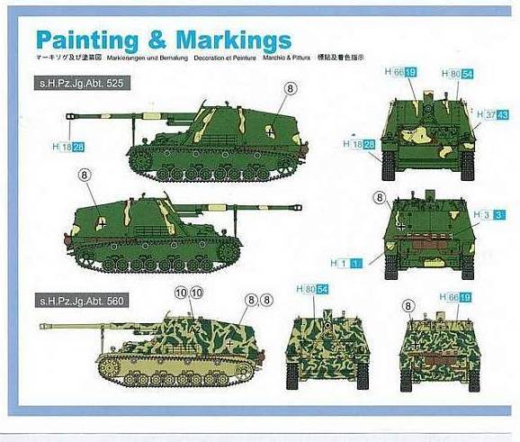
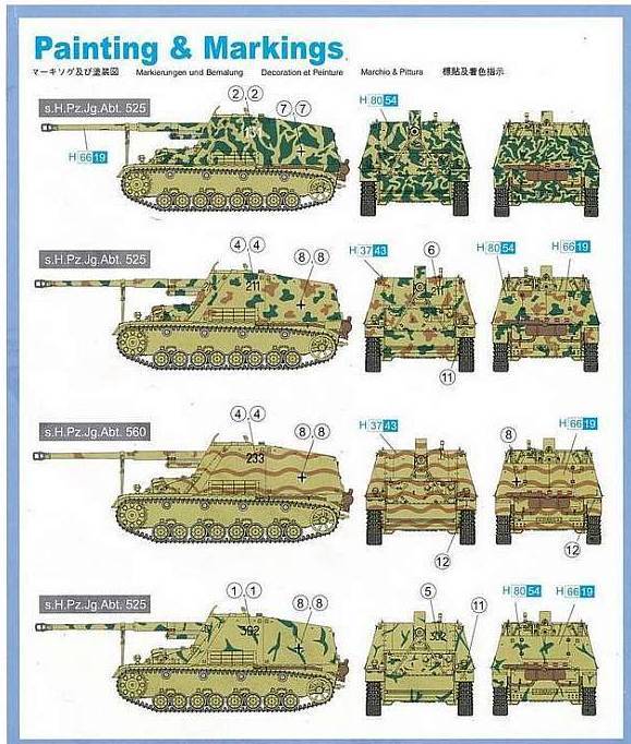
The kit offers markings for six vehicles. The description is markedly
more concise than in the Nashorn kit.
Pictures
from Henk
of Holland website, used with permission.
- A
three-color vehicle from s.H.Pz.Jg.Abt.525 with only some Balkenkreuze.
- “A2”
from s.H.Pz.Jg.Abt.560 (probably the Stabskompanie). Dark yellow
with green blotches. See discussion below.
- “131”
from s.H.Pz.Jg.Abt.525. Strangely it has the exact same camouflage
pattern as the vehicle above, which is from a different unit. This
might be the vehicle shown on page 39 of [1], but then it needs
its number repeated on the gun shield (standard practice in this
unit) and the numbers would need to be black. It uses the early
drive sprocket and I believe it uses the early barrel lock. I can't
see the muffler arrangement.
- “211”
from s.H.Pz.Jg.Abt.525 in three colors in almost exactly the same
pattern as “131” in the Nashorn kit. This vehicle is
shown on page 37 and 38 of [1] and on page 48 of [2]. The placement
of the markings seems to be correct and the camouflage pattern might
be as well. However it uses the late barrel lock and early drive
sprockets, and it seems to have a late layout of rear fenders (and
thus probably of the muffler), which means the modeler would better
build it using the Nashorn kit.
- “233”
from s.H.Pz.Jg.Abt.560 with wavy brown bands on a dark yellow background
in exactly the same pattern as “211” in the Nashorn
kit. See discussion below.
- “302”
from s.H.Pz.Jg.Abt.525. Dark yellow with green blotches. This vehicle
is shown on page 37 of [1]. The placement of the markings seems
to be correct and it also seems to be an early vehicle, but the
camouflage might have been different.
The kit
offers spare decals and individual numbers in different styles.
Incidentally,
the Dragon decals didn't adhere very well, even after the use of setting
solutions and are very fragile.
2./s.H.Pz.Jg.Abt.560
Dragon
offers three options of 2./s.H.Pz.Jg.Abt.560, as follows
- 231
(Nashorn kit) – brown wavy bands
- A2
(Hornisse kit) – green blotches
- 233
(Hornisse kit) – brown wavy bands
The pictures
that best match these, and that I could find, are on page 34 and 35
of [1] where the vehicles of the unit are entrained. Looking closely
at the pictures, the following features could be identified of the
individual vehicles:
| Code |
? |
A2 |
? |
? |
2?? |
? |
211 |
232 |
231 |
| Spare
roadwheel |
Front |
Front |
Not
at rear |
? |
? |
Not
at rear |
Front |
Not
at front |
? |
| Drive
sprocket |
New |
New |
New |
? |
New |
? |
New |
Old |
? |
| Muffler |
? |
? |
Old |
? |
? |
Old |
? |
? |
? |
| Mudflaps |
? |
? |
Yes |
Yes |
Yes |
Yes |
Yes |
Yes |
Yes |
| Box
with mudflaps |
? |
? |
No |
Yes |
No |
No |
No |
Yes |
No |
| Barrel
lock |
new |
new |
? |
? |
? |
? |
new |
? |
? |
| Appliqué
armor on gunshield |
? |
? |
? |
? |
? |
? |
No |
Yes |
? |
All vehicles had a box on the right front fender and
all seem to have had mudflaps, even the vehicles with the late exhaust
and without the boxes under the rear fenders. Presumably, this is
a field modification.
This means that at least the following should be considered when building
the vehicles that Dragon offers:
- 231
(Nashorn kit): add mudflaps. The camo matched the instructions.
- A2
(Hornisse kit): start from the Nashorn kit and add spare roadwheels.
The camo is roughly in line with the instructions.
I decided
to build my Hornisse as 233 which I didn’t find in the pictures
to give me some margin for maneuver.
Compared with the Dragon instructions I
- painted
thicker wavy brown bands. The camouflage on the vehicles seems to
have been quite variable and the nozzle of my airbrush was getting
too worn to paint them any thinner.
- I
didn’t use the symbol of a self-propelled anti-tank unit on
front and rear. Basically, because I forgot.
- I
added kill rings to the barrel (from the spares box). Not that this
is a typical feature of the unit.
Compared
with the features of other vehicles of the unit I didn't add the box
on the fender.
_t.jpg) _t.jpg) _t.jpg)
The figure is
from Preiser.
For details
about other units that used the Nashorn, see [1].
References
[1] Greenland, T., & Terlisten, D. (2001). Nuts & Bolts Vol.
14: Nashorn – Pz.Jäger Nashorn & 8.8 Pak 43/1 –
Sd.Kfz. 164. Nuts & Bolts Verlag Gbr.
[2] Ledwoch, J. (2010). Nashorn (Wydawnictwo Militaria No. 334, Tank
Power Vol. XCIII). Wydawnictwo Militaria.
[3] Jentz, T. L., & Doyle, H. L. (2006). Panzer Tracts No. 7-3:
Panzerjäger (7.5 cm Pak 40/4 to 8.8 cm Waffenträger). Panzer
Tracts.
[4] Feenstra, J. (2017). Panzerjäger on the Battlefield (World
War Two Photobook Series Vol. 15). PeKo Publishing Kft. ISBN 978-615-5583-07-0.
[5] Ellis, C. (2011). PzKpfw IV at the front, Vol 5: Variants. 8wheels-good.
ISBN 978-0-9563655-4-5.
Review
samples purchased by the author. |


.jpg)
.jpg)
.jpg)
.jpg)
.jpg)
.jpg)
.jpg)
.jpg)
.jpg)
.jpg)
.jpg)
.jpg)
.jpg)
.jpg)
.jpg)
.jpg)
.jpg)
.jpg)
.jpg)
.jpg)
.jpg)
.jpg)
.jpg)
.jpg)
.jpg)
.jpg)
.jpg)
.jpg)
.jpg)
.jpg)
.jpg)
.jpg)
.jpg)
.jpg)
.jpg)
.jpg)
.jpg)
.jpg)
.jpg)
.jpg)
.jpg)
.jpg)
.jpg)
.jpg)
.jpg)
.jpg)
.jpg)
.jpg)
.jpg)
.jpg)
.jpg)
.jpg)
.jpg)
.jpg)
.jpg)
.jpg)
.jpg)
.jpg)
.jpg)
.jpg)
.jpg)
.jpg)
.jpg)
.jpg)
.jpg)
.jpg)
.jpg)
.jpg)
.jpg)
.jpg)
.jpg)
.jpg)
.jpg)
.jpg)
.jpg)
.jpg)
.jpg)
.jpg)
.jpg)
.jpg)
.jpg)
.jpg)
.jpg)
.jpg)
.jpg)
.jpg)
.jpg)
.jpg)