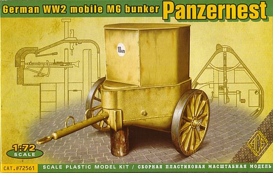
|
A brief history
From [1]:
"The MG Panzernest was developed in the second half of the war and was used extensively in Italy (as well as the Eastern and Western Front - ed.). The thick upper armour provided valuable protection for the
two-man crew and the nest was easily transported with the opening at the front doubling as the housing for the towing limber and the holes for the ventilation
acting as the mounting for an axle, which was then fitted with two wheels. The position was designed to mount a machine gun that could fire through the small
aperture in the front. This limited the weapon's traverse and meant that it only had a 60-degree field of fire. When the position was not in use the opening
could be covered with a shield. The crew gained access to the position via a hatch at the rear and two periscopes in the roof provided them with observation.
When they were firing the machine gun the fumes were extracted by a simple foot-operated ventilation system."
Installing the Panzernest in its position required digging a hole, pushing the Panzernest while on its wheel to the edge and then tipping it into place. Then it
was adjusted for position and the remainder of the hole filled. The position then was equipped with its gun and other necessities. Supplemental camouflage
was often used afterward to further protect and disguise the Panzernest.
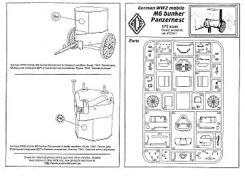
The kit
Inside the box is a single small sprue with 66 parts molded in a nice light grey colour. The plastic is softish but not as soft as Ace's older kits molded
in white plastic. There is a minuscule decal sheet with two images. Pictures of the sprues and decal sheet can be found on
Henk of Holland's site.
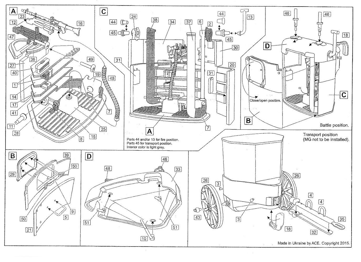
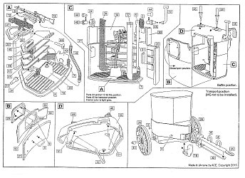
A small instruction sheet rounds out the contents. It is printed on two sides, with 6 exploded parts style diagrams
outlining the construction sequence. The diagrams are cramped and too busy for my liking (see below). Painting guide offers two schemes - overall
Panzer grey or overall Panzer yellow. Period photos show both dark and light coloured bunkers so it seems that both options are probably valid.
Forget the instructions as they're laid out. For me Ace's build sequence is just a potential recipe for disaster and construction options are presented in odd places.
Many of the parts
are best added later or added first to a different part versus that suggested. A good example comes right from the start in Step A, where the MG 34, its mount
and the race are added, but there's no
indication as to where, or to what, they are attached to. You have to look at the diagram in Step C to see that the gun's race actually spans the space between the
the left and right walls, where there are two small nubs for it to rest on.
With that in mind, what follows is my build sequence which seemed to work quite well for me.
1. Start with the floor. Add these parts: 7, 8, 19, 25 & 28. The pedals used for evacuating gun fumes (part 8) is incorrect.
It should be layed out like a bicycle, with the pedals 180o opposed from each other. I cut off one pedal and
re-attached it in the proper position.
2. Build up the walls. Glue together the right wall (part 20 - lower section & part 30 - upper section) and then
add it to the floor. Glue the nose piece (part 47) to the front wall (part 27) and join them to the floor and the
right wall. Glue together the left wall (part 22 - lower section & part 34 - upper section) and then
join it to the floor and the front wall. Note: parts 22 & 34 for the left wall are not labeled in the Ace instructions, Step C.
Then add parts 31 (which I believe are seats), part 38 (intake for the ventilation system) and part 11. I actually replaced part 11
with new scratch built pieces because it had major seams and was so out of round that I felt it was easier to make new parts than clean up
the kit part. Besides, it didn't look like it was long enough to span the gap between parts 28 & 38 anyway.
Ace would have you mount the shelves to the front wall at first in Step A. Not a good idea. I waited until this point to remove them from the sprue
so I could check their fit between the walls and adjust as needed. Then they were left separate to be painted later. These shelves are metal so there is no
need to paint them to simulate wood like I've seen in a lot of 1/35 scale Panzernest reviews.
3. Assemble the rear wall as per Step B of the instructions. Ace would have you mount the door closed, but if you want to see anything of the interior
then it obviously needs to be mounted open. To do this make sure the dogs (part 50) are displaced appropriately. Check references pictures to see
how these are mounted. The dogs are a bit thick and could be replaced if desired. I didn't bother. I added the outlet for the ventilation
system (part 37) here.
4. Construct the roof as per Step D of the instructions. Make sure that the handle for the embrasure cover (part 18) is displaced to one side if you
plan to build the kit with the tongue inserted into the gun opening for towing. The periscope covers (part 48) have to be either turned to the rear for
the periscopes (part 46) to poke through if you want the Panzernest in combat position, or over the periscope openings if the Panzernest is to be in towed
position. This is where I added parts 2 & 24 (wheel axle mount) directly to
the roof as opposed to Ace's suggestion to add them in Step C.
The upper walls and roof appears to be cast metal so I roughed up their interior surfaces. At this point I also built the tongue and cleaned up the wheels, their hubs
and the embrasure cover.
5. At this point I suggest painting the interior, and other loose interior parts - the aforementioned shelves and part 6. Ace suggests light grey for the colour.
I think it's closer to white based on the few reference pictures I could find. I masked the joining surfaces of the sub-assemblies to ensure a strong glue joints.
6. Once the interior is painted the sub-assemblies can be joined together. Before doing this add the MG mount (parts 12 & 23) and race (part 36). I had to trim some from
the front of MG mount to get it to fit. If the bunker is to be in combat mode also add
the MG34 and the spent casing chute (part 48) now. It should be noted that the MG 34 supplied by the kit is a bit anemic and would be best replaced. Some references state
that an MG 42 was also used, but others state that it wasn't because the fumes it emitted overwhelmed the ventilation system. I believe the latter is true.
To join the sub-assemblies I started with the roof to the wall & floor, then added the rear wall, after gluing part 6 in place
first. I found part 6 a tad too long so it was trimmed to fit. As mentioned above, the upper part of the Panzernest appears to be cast metal,
so exterior was roughed up to simulate a cast texture. The lifting pegs (part 3) can be added now.
7. With the main body together the remaining pieces can be added depending upon which option is chosen.
For combat add the plugs (part 44) to the axle mounts. I think that the Ace instructions are in error here, and only the left plug should be used, with the right one
being discarded so that the vent tube (part 13) can take its place. Make sure to drill out the horizontal tube of the vent, from end to end. The periscopes can
be added and Ace has saved the modeller some effort here by already having their openings represented as nice rectangular depressions.
If the bunker is to be towed then use the axles (part 45) in place of the plugs, and add the towing tongue and wheels. The embrasure cover will have to be displaced
to the side. Make
sure that it correlates to the position of its handle on the inside.
Some other minor points to consider:
- Step A directs the modeller to add the ammo canisters (parts 1 & 40) to the shelves. I would think that while the Panzernest is being towed in its
upside down travel position these would not be there as they'd fall and rattle around inside during movement.
- Most photos of Panzernests show casting numbers on the exterior of the left and right walls. I replicated these by slicing off some sprue numbers
and gluing them to the walls.
- There are weld lines on the vertical seams that I represented with thin plastic rod, softened with liquid glue and then marked up with the edge of a
hobby knife blade.
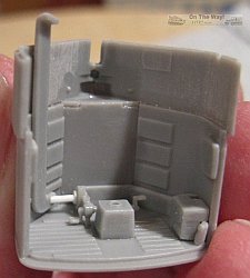
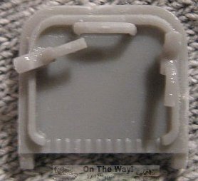
Inside of the Panzernest. You can see
how I modified the pedals so one is up
and the other is down. The ventilator
intake is mounted to the left wall.
|
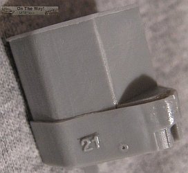
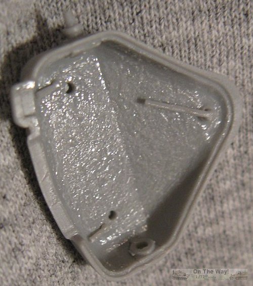
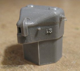
At left, is the casting numbers applied to the exterior.
At right is the interior of the roof. I have roughed it
up to replicate cast metal. Notice how the embrasure cover
handle has been displaced since I will eventually mount
the cover to point the opposite direction. |
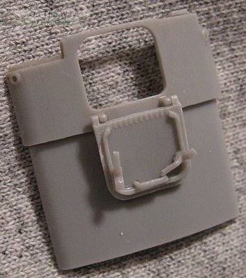
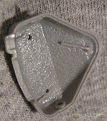
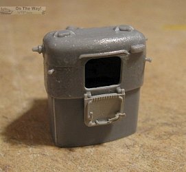
Rear wall with the hatch friction fit in place
to show how it sits when open. The exit
for the ventilation system can just be made
out in the upper right corner.
|
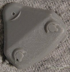
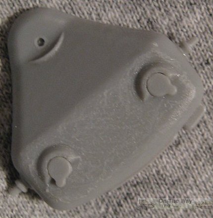
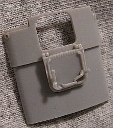
Top side of the roof. I have glued the
periscope covers over the openings since
my Panzernest will be in towed mode.
|
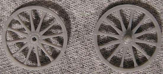
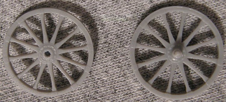
These are the wheels. Unfortunately each spoke and the arc
between them suffers from seams that need to be removed.
Otherwise they are nicely detailed. |
The inside of the hatch has nice detail
as well. The dogs are a bit thick though.
|
Left side view of
the completed Panzernest body.
|
Right side view of
the completed Panzernest body.
|
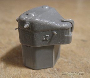
Rear view of the completed Panzernest
body. All the beautiful interior detail
is in the dark and next to impossible to
see without a flashlight!
|
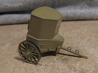
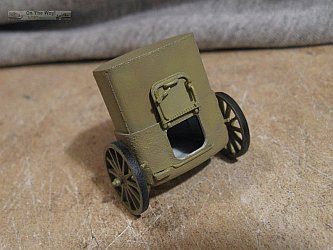
Panzernest in towed mode. The wheels, tongue & hatch have been attached loosely to see how the
completed kit will eventually look. The sole decal has been applied with no problems encountered.
|
The following Panzernest measurments are based on an indistinct diagram found at [6]:
| 1:1 Height | 1:1 Width | 1:1 Length |
| 190cm | 167cm | 167cm |
| 1:72 Height | 1:72 Width | 1:72 Length |
| 2.64cm | 2.32cm | 2.32cm |
| Kit Height | Kit Width | Kit Length |
| 2.7cm | 2.32cm | 2.35cm |
| Kit Scale Height | Kit Scale Width | Kit Scale Length |
| 1:70 | 1:72 | 1:71 |
Conclusion
I have a few of Ace's earlier kits in my stash, and have built some as well, and they are in
my opinion not much for quality. Detail is soft and you pretty much have to carve each part out of
the copious flash surrounding it and remove the ubiquitous and prominent seams. Once the part was ready, fit was usually marginal and straightness not a strong suit,
but...
... with this kit, Alexey's quality exhibits a big, and I do mean big, step forward. Further research shows that his
newer model kits, in the 725xx series and above, appear to be much more detailed, better fitting and the copious amounts of flash and prominent seams
have been reduced extensively. Now I do have to say that Alexey's kits are nowhere near the quality of what you get with Flyhawk, the company that I currently consider
to be the "King of the Hill" for braille model kits right now, but I no longer get the heebie-jeebies when I consider ordering one of the more recent kits from Ace. I
can honestly say that I thoroughly enjoyed building this Panzernest.
So, Alexey, I tip my hat to you. Your labours toward improving your product line has paid large dividends. I will seriously consider buying more of your newer releases.
References
[1] German Defences in Italy in World War II: Osprey Fortress 45, Neil Short, Osprey Publishing, Oxford, UK 2006 ISBN10: 1-84176-938-X ISBN13: 978-1-84176-938-7
[2] theminiaturespage.com
[3] histomil.com
[4] amps-armor.org (review of the Verlinden 1/35 Panzernest)
[5] forum.axishistory.com (forum thread on Panzernests)
[6] forum.axishistory.com (another forum thread on Panzernests)
[7] handmet-military.net
[8] www.przemkko.strefa.pl
[9] Ace Models
Review sample purchased by the author.
Ace products are available at

|